Fondital TAHITI CONDENSING IST 03 C 298 - 02 Скачать руководство пользователя страница 23

23

3.2.4.  

Installing the boiler

Before connecting the boiler to CH and DHW networks, clean the pipes carefully.

Prior to operate a NEW system eliminate any metallic leftover during manufacturing and welding process, and any oil or 

grease deposits, which might reach the boiler and damage it or alter its operation. 

Prior to operate a MODERNIZED system (addition of radiators, boiler replacement, etc.), clean it throughout so as to remove 

possible sludge and foreign particles.

In order to clean the system, employ non acid product available on the market. Do not use solvents as they could damage 

system components.

Furthermore, in the central heating system (either new or modernized), it is always advisable to add to water, with adequate 

concentration, suitable products inhibiting corrosion in multi-metal systems, which produce a protective film on internal 

metal surfaces. 

Manufacturer shall not be held responsible in case of harm to people and/or animals, or property damage due to failure in 

adhering to the above stated instructions.

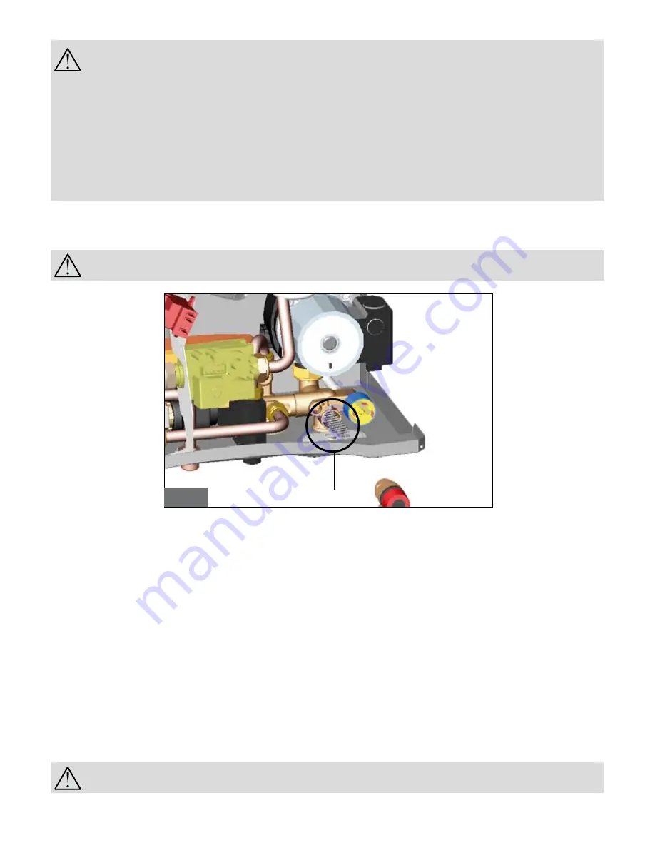
The boiler is fitted with a filter (fig. 11) whose function is to prevent the main heat exchanger pipes from obstructing, due to deposits that may form 
in the heating system.
Such filter is not sufficient to prevent deposits of such materials to form inside the boiler. To this purpose, please note that:

For all boiler installation types, it is necessary to install a filter which can be inspected (Y-shaped type) with Ø 0.4mm-mesh 

span, on the return pipe before the boiler.

In order to install the boiler proceed as follows:
• affix the template (fig. 10) to the wall;
• drill two 12 mm Ø holes in the wall to accommodate the boiler support bracket wall plugs;
• arrange air intake/flue gas system path in the wall as needed;
• secure boiler support bracket to the wall by means of the wall plugs supplied with the boiler;
• position gas supply network coupling 

G

, water mains supply coupling 

(KC and KR models), 

RB

 secondary return from the boiler (only KRB 

model), DHW flow coupling 

C

 (only in KC model), 

MB

 secondary flow to the boiler (only KRB model), CH flow coupling 

M

, and CH return coupling 

R

, as shown on the template (refer to its lower area);

• provide a system for relieving condensates (S in fig. 10) and an outlet for the 3-bar safety valve (SV in fig. 6);
• position the boiler to the supporting bracket on the wall;
• connect the boiler to network pipes by means of the coupling kit supplied with the boiler (refer to 3.2.9. paragraph);
• connect the boiler to pipe for condensate discharge (refer to 3.2.9. paragraph);
• provide a system for relieving the 3-bar safety valves;
• connect the boiler to the air intake and flue gas exhaust system (refer to 3.2.6. paragraph and following);
• connect electric power supply, room thermostat (when available) and other available accessories (refer to the following paragraphs). 

3.2.5.  

Boiler room ventilation

The boiler has sealed combustion chamber. Combustion air is not drawn from boiler room, therefore specific recommendations need not to be 
applied concerning the boiler room or openings and ventilation provided to the boiler room.

It is mandatory to install the boiler in an adequate room following laws and standards applicable in the country of 

installation, which are considered as fully transcribed in this manual.

fig. 11

Filter

Содержание TAHITI CONDENSING IST 03 C 298 - 02

Страница 1: ...IST 03 C 298 02 INSTALLATION USE AND MAINTENANCE TAHITI CONDENSING GB...

Страница 2: ...one of our boilers Please read these instructions carefully in order to properly install operate and maintain the equipment The Manufacturer recommends that Customers contact authorized qualified per...

Страница 3: ...ackaging out of the reach of children as it may represent a source hazard In the event of failure and or faulty functioning switch off the boiler Do not attempt to make repairs contact qualified techn...

Страница 4: ...water temperature 4 If you wish to activate the heating function turn the boiler selector 2 fig 1 to WINTER This will activate both DHW and heating and the display will show the flow water temperature...

Страница 5: ...1 3 2 Installation page 21 3 2 1 Packaging page 21 3 2 2 Choosing where to install the boiler page 21 3 2 3 Positioning the boiler page 21 3 2 4 Installing the boiler page 23 3 2 5 Boiler room ventila...

Страница 6: ...tral heating curves with external probe operation page 33 fig 24 System head curves page 35 fig 25 Wiring diagram page 36 fig 26 Adaptation to other gas types page 38 fig 27 Gas valve adjustment page...

Страница 7: ...ble disable water storage and to set the DHW temperature in the range 35 57 C For KR boiler with an external optional water heater this regulator also activates deactivates the heater For boilers mode...

Страница 8: ...n when the burner shutdown device activates due to a malfunction To restart the boiler turn the boiler selector 2 fig 1 to the RESET position for a few seconds and then back to the desired position g...

Страница 9: ...ptional water heater Table 1 BOILER STATUS LCD visualisation correspondence normal operation Malfunction Boiler not powered on Boiler shutdown due to flame absence Boiler shutdown due to safety thermo...

Страница 10: ...h depends on the selected operating range standard range 4 minutes reduced range 2 minutes Should water temperature in the system fall below the default value see 3 2 11 paragraph waiting time procedu...

Страница 11: ...de on selector 2 When the heating water temperature sensor detects a water temperature of 5 C the boiler switches on and stays on at its minimum thermal power until the temperature reaches 30 C or 15...

Страница 12: ...nd the temperature setting is displayed Regulator 4 in the fully anticlockwise position corresponds to a fictitious room temperature of 15 C 9 o clock corresponds to 18 C 12 o clock to 25 C 3 o clock...

Страница 13: ...flue gas system malfunction If the air flue gas system malfunctions the boiler shuts down The burner shutdown symbol is displayed and code E03 flue gas thermostat Contact an Authorised Service Centre...

Страница 14: ...If the optional external temperature probe malfunctions the boiler shutdown symbol is displayed and code E23 flashes The boiler will continue to operate but the sliding temperature function is deacti...

Страница 15: ...uid crystal display showing the boiler operating status Mode selector OFF RESET WINTER SUMMER and ANTI FREEZE CH water temperature regulator 20 78 C standard range or 20 45 C reduced range DHW water t...

Страница 16: ...illing tap R CH system return RS Drain cock MB Secondary flow to the boiler only KRB model 71 43 56 98 75 98 80 138 177 46 G M MB RB RC R SV SI View from the bottom of models KC and KR View from the b...

Страница 17: ...n G Gas intake M CH system flow C DHW flow F Water mains intake R CH system return 1 Condensate drain siphon 2 Modulating gas valve 3 Safety thermostat 4 CH temperature probe 5 Modulating fan 6 Primar...

Страница 18: ...lue gas thermostat on discharge duct 14 Flue gas thermostat on exchanger 15 Flame sensing electrode 16 Expansion vessel 17 Fan management probe 18 Air purging device 19 Pump 20 3 bar safety valve 21 U...

Страница 19: ...C kW CH output 50 30 C kW DHW output kW Gas mains pressure mbar Diaphragm diameter mm Flue gas CO2 min max min max min max Methane Gas G20 31 4 8 7 30 63 9 6 33 2 9 6 35 4 20 8 4 8 8 9 1 Propane Gas...

Страница 20: ...rating 30 50 C 104 8 Minimum heat output efficiency rating 60 80 C 95 7 Minimum heat output efficiency rating 30 50 C 106 9 30 heat output efficiency rating 109 1 Efficiency rating according to 92 42...

Страница 21: ...s for fixing the metal plate to the wall 3 2 2 Choosing where to install the boiler The following must be taken into account when choosing where to install the boiler 3 2 6 Air intake flue gas dischar...

Страница 22: ...22 fig 10...

Страница 23: ...roceed as follows affix the template fig 10 to the wall drill two 12 mm holes in the wall to accommodate the boiler support bracket wall plugs arrange air intake flue gas system path in the wall as ne...

Страница 24: ...or condensing boiler are to be used Flue gas discharge pipes are to be installed tilted toward the boiler so that condensate runs in the direction of the combustion chamber which is designed for conde...

Страница 25: ...ore the combustion chamber heat exchanger Type C33 Boiler intended for connection to vertical outlet and intake ducts connected to the outside by means of coaxial or split ducts The distance between a...

Страница 26: ...t elbow connected to the boiler Maximum permissible length of 125 80 mm horizontal coaxial pipes is 11 5 meter not including the first elbow connected to the boiler For each additional 1 meter of stra...

Страница 27: ...229 5 139 5 80 148 148 3 2 7 Testing combustion efficiency 3 2 7 1 Chimney sweep function The boiler is equipped with chimney sweep function to be used when testing combustion efficiency and in order...

Страница 28: ...ipe size calculation depends on its length layout pattern gas flow rate Gas pipe size is to be dimensioned accordingly Comply with installation standards enforced in the installation country which are...

Страница 29: ...Comply with condensate drain laws and standards applicable in the country of installation which are considered herein integrally transcribed When the law is not stating differently the condensate pro...

Страница 30: ...e boiler can be connected to an OpenTherm remote control an optional supplied by the manufacturer The remote control must be installed by a suitably qualified person Only original remote controls supp...

Страница 31: ...with power cables The temperature probe must be installed on an outside wall facing north or north east in a position protected from atmospheric agents Do not install near a window ventilation openin...

Страница 32: ...TSP5 17 Fig 23 shows the curves for a fictitious temperature of 20 C When this value is increased or decreased via regulator 4 the curves move up or down respectively With a temperature setting of 20...

Страница 33: ...rewdriver in the hole and rotate the circulation unit shaft clockwise Once the unblocking operation has been completed screw the protection bolt back on and check for water leaks When the protection b...

Страница 34: ...0 200 400 600 800 1000 Modello KC32 KR32 Portata l h Velocit 3 Velocit 2 Velocit 1 MODEL KR KC KRB 24 Flow rate l h MODEL KR KC KRB 28 MODEL KR KC KRB 32 Flow rate l h Flow rate l h Load loss mbar Loa...

Страница 35: ...equipped by external heater with NTC probe and temperature regulation on the boiler Only KC Only KC Only KC and KRB IMPORTANT 1 It is necessary to quit the TA jumper connector M9 2 In case of thermor...

Страница 36: ...TF1 TF2 flue gas thermostat protecting discharge system and exchanger TR ACC ignition transformer SR CH probe 10k Ohm B 3435 SE external temperature probe 0SONDAES01 10k Ohm B 3977 Option boiler prob...

Страница 37: ...nnection to the gas valve A in fig 26 see par 3 7 3 3 7 3 Burner adjustment Maximum heating output adjustment set max heating output adjuster max fig 18 to maximum turn it fully clockwise the LCD will...

Страница 38: ...is designed If necessary convert the boiler following the instructions in subsection 3 7 ADAPTATION TO OTHER GASES AND BURNER ADJUSTMENT This operation must be carried out by a qualified service engin...

Страница 39: ...State of combustion fan General integrity of the boiler safety devices Integrity state of preservation and seal of the flue gas discharge pipes Water leaks and oxidation of the boiler fittings Boiler...

Страница 40: ...and code E02 flashes Operation can be resumed by resetting the pressure in the system Boiler safety thermostat has cut in CH water does not flow pipes might be clogged thermostatic valves might be sh...

Страница 41: ...f shutdown has been removed Combustion fan not working Fan disconnected Reconnect it Fan faulty Replace it The optional remote control is switched off The symbol is displayed and code E22 flashes Oper...

Страница 42: ...42...

Страница 43: ...43...

Страница 44: ...78 576 e mail fondital fondital it www fondital it Il produttore si riserva il diritto di apportare ai propri prodotti quelle modifiche che riterr necessarie o utili senza pregiudicarne le caratterist...

Отзывы: