background image

HCD710A, HMD710A 

25

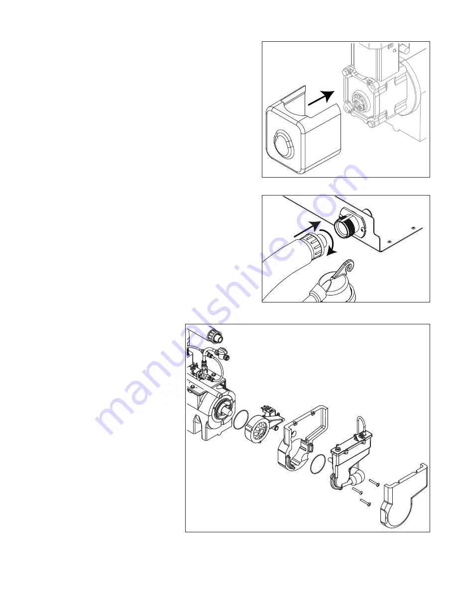
Fig. 33 

35. Install gear motor insulation.

Fig. 34 

36. Connect transport tube to louvered docking assembly.

Reservoir/rear bushing disassembly

Fig. 35 

1.  Press CLEAN button to purge 

evaporator. Turn power OFF 
when LO WATER lights.

Note: In many applications, 

removing the gearmotor, 
main housing, and 
auger will allow for 
the ice machine to be 
pulled out further for 
better access to rear 
components.

2.  Slide ice machine forward to 

gain access.

3.  Use Fig. 35 as disassembly 

guide.

Note: Use petrol-gel when 

installing/reinstalling 
o-rings.

Содержание HCD710ABS

Страница 1: ...ontained 801 Church Lane Easton PA 18040 USA Toll free 877 612 5086 1 610 252 7301 www follettice com Following installation please forward this manual to the appropriate operations person Operation a...

Страница 2: ...arvest system diagram 11 Water system diagram 13 Water level diagram 13 Normal control board operation 14 DIP Switch Settings 14 Error faults 15 Soft errors 15 Hard error 15 Run errors 15 Relay output...

Страница 3: ...isk of shock disconnect power before servicing Drain line must not be vented Water supply must have particle filtration Most ice machine cleaners contain citric or phosphoric acid which can cause skin...

Страница 4: ...commended within 10 feet 3m Water supply must have particle filtration Follett recommends the filter system that has integral scale inhibitors Follett item 00130286 Follett does not recommend the use...

Страница 5: ...led ice machine capacity 24 hrs Ambient Air Temperature F C Evap Potable Water Temperature F C F 60 70 80 90 100 C 16 21 27 32 38 50 787 759 705 639 603 lbs 10 357 344 320 290 274 kg 60 750 702 666 62...

Страница 6: ...ns connections to allow removal 1 26 mm clearance above ice machine for service 1 26 mm minimum clearance on sides The intake and exhaust air grilles must provide at least 250 sq in 1615 sq cm of open...

Страница 7: ...are The exterior may be cleaned with a stainless cleaner such as 3M Stainless Steel Cleaner Polish or equivalent Monthly condenser cleaning air cooled icemaker only 1 Use a vacuum cleaner or stiff bru...

Страница 8: ...until CLEANER FULL light comes on Do not overfill 4 Soak one SaniSponge in remaining sanitizing and cleaning solution and retain for Step 9 Note Do not use bleach to sanitize or clean the icemaker CLE...

Страница 9: ...oupling as shown Fig 6 8 Using disposable food service grade gloves insert dry SaniSponge 9 Insert SaniSponge soaked in SafeClean Plus from Step 4 10 Push both SaniSponges down ice transport tube with...

Страница 10: ...12 Reconnect coupling Press power switch ON Ice pushes SaniSponges through ice transport tube Fig 9 13 Place a sanitary 2 gal or larger container in bin or dispenser to collect SaniSponges and ice for...

Страница 11: ...s extrusion process pushes the Chewblets through a transport tube into a dispenser or bin A solid state PC board controls and monitors the functionality of the ice machine In addition to sequencing el...

Страница 12: ...of the flag is down and the switch is closed When the bin fills to the top and ice can no longer move through the tube the machine will force the shuttle flag up opening the switch and shutting the ma...

Страница 13: ...the activation During normal operation the water level rises and falls between the Normal High and Normal Low probes As water is consumed to make ice the level will fall until the Normal Low probe is...

Страница 14: ...ll lock the machine off A flashing green light labeled POWER indicates power to the machine All other normal operation status indicators are covered as follows Ice machine disposition Operating condit...

Страница 15: ...are dried off the machine must be reset on the control board to resume operation Run errors DRAIN CLOG When the machine shuts down on a full bin and there has been 30 minutes of cumulative compressor...

Страница 16: ...16 HCD710A HMD710A Wiring diagram...

Страница 17: ...sor start winding 120 V 2 23 Compressor run winding 120 V 0 32 Gearmotor data Gearmotor current 1 2A 120 V Gearmotor torque out high amp trip point 1 8A 120 V Resistance of windings 115 vac gearmotor...

Страница 18: ...n to purge evaporator Turn power OFF when LO WATER lights 2 Unscrew and disconnect transport tube from louvered docking assembly Fig 11 3 Remove gear motor insulation Fig 12 4 Disconnect gear motor wi...

Страница 19: ...A HMD710A 19 Fig 14 6 Remove spacer Fig 15 7 Remove gear motor bolts 1 2 wrench 8 Remove gear motor and wipe auger shaft clean WIPE AUGER SHAFT Fig 16 9 Remove main housing insulation and shuttle insu...

Страница 20: ...tting shuttle drain tube and shuttle switch Fig 18 11 Remove 3 screws with 3 16 allen wrench then remove auger and main housing together Note Auger is sharp wear protective gloves Fig 19 12 Rotate aug...

Страница 21: ...emature seal failure 16 Use liquid hand soap on the rubber part of the ceramic seal when installing in main housing Use supplied cardboard disc to press into recess 17 Apply liquid hand soap to raised...

Страница 22: ...ing Fig 23 2 onto auger 22 Secure with three screws 1 2 Fig 24 23 Install shuttle switch Align holes with pins Fig 24 1 and depress switch button Fig 24 2 to clear shuttle tab Fig 25 24 Install shuttl...

Страница 23: ...uger shaft 27 Slide gear motor onto auger and install gear motor bolts 1 2 wrench APPLY PETROL GEL Fig 28 28 Use screwdriver to pry auger shaft foward then orient auger shaft to align with motor shaft...

Страница 24: ...auger shaft and pry shaft outwards Fig 30 1 32 Insert retainer into groove Fig 30 2 ensure that retainer is aligned with hole in spacer 1 2 Fig 31 33 Install screw and tighten Fig 31 1 1 Fig 32 34 Co...

Страница 25: ...s CLEAN button to purge evaporator Turn power OFF when LO WATER lights Note In many applications removing the gearmotor main housing and auger will allow for the ice machine to be pulled out further f...

Страница 26: ...tion charge All service on refrigeration systems must be performed in accordance with all federal state and local laws It is the responsibility of the technician to ensure that these requirements are...

Страница 27: ...valve inlet Ice capacity test Ice machine production capacity can only be determined by weighing ice produced in a specific time period 1 Replace all panels on ice machine 2 Run ice machine for at le...

Страница 28: ...n 3 Ice machine is not making ice HI AMPS 1 Poor water quality causing ice to jam auger 2 Drain not draining slow to drain 3 Damaged shuttle mechanism 4 Intermittent drive output from PC board Evapora...

Страница 29: ...ing ice Lo water 1 Water supply is insufficient 2 Low water pressure 3 Defective water feed solenoid valve Stuck in closed position 4 No water feed output from PC board 5 Plugged screen on inlet side...

Страница 30: ...CD710A HMD710A Replacement parts Evaporator assembly 27 3 36 10 2 8 3 21 5 2 1 14 13 12 11 9 29 7 20 15 16 18 22 23 31 31 31 31 31 19 13 24 25 26 28 28 4 10 2 31 17 17 17 17 17 34 33 35 30 32 2 31 31...

Страница 31: ...ed 01223015 19 Reservoir lid and sensors includes screws and o ring 01118108 20 Valve shut off water 502921 21 Auger 710 self contained includes seal key and auger hardware 01222686 22 Evaporator 710...

Страница 32: ...32 HCD710A HMD710A 9 1 8 7 6 4 5 3 2 Air cooled assembly...

Страница 33: ...222793 3 Cut out high pressure safety 01222007 4 Insulation bulb TXV 00106534 5 Drier 00134593 6 Valve expansion thermal includes insulation and 2 clamps 01222777 7 Insulation TXV body and bulb 502830...

Страница 34: ...34 HCD710A HMD710A Electrical box 1 4 3 2 7 5 6 8...

Страница 35: ...ectrical box air water cooled 01118967 2 Board control includes stand offs 01222827 3 Stand offs set of 8 00130906 4 Supplied with gear motor 5 Switch evaporator clean 01165703 6 Switch ice machine po...

Страница 36: ...36 HCD710A HMD710A Integration kit top mount and RIDE remote ice delivery 1 11 2 2 13 10 12 4 5 7 8 12 1 11 10 2 9 4 5 6 7 8 2 6 3 3 RIDE model configuration Top mount configuration 14 14...

Страница 37: ...3 m of tube and insulation 00171397 Not shown Integration kit drop in 00145334 Not shown Integration kit Cornelius PR150 00144774 Not shown Integration kit Vision does not include ice tube 00997171 N...

Страница 38: ...38 HCD710A HMD710A Skins assembly 9 8 10 2 1 11 7 5 4 3 6...

Страница 39: ...ut 00145342 7 Hose clamp 500377 8 Plate strain relief 00192070 9 Louvered docking station 710 includes strain relief plate bulkhead fitting 01119031 10 Screw 203460 11 Bulkhead connector kit 00171223...

Страница 40: ...cutif de toute d pense de tout frais de raccordement ou de d connexion ni de toute perte li e un d faut de la machine Pour lire la garantie dans son ensemble visitez notre site Internet www follettice...

Отзывы: