background image

                                          FMUSER INTERNATIONAL GROUP INC. 

广州市汉婷生物技术开发有限公司


1

 / 

42


Chapter 1 Product Outline   

1.1 Outline 

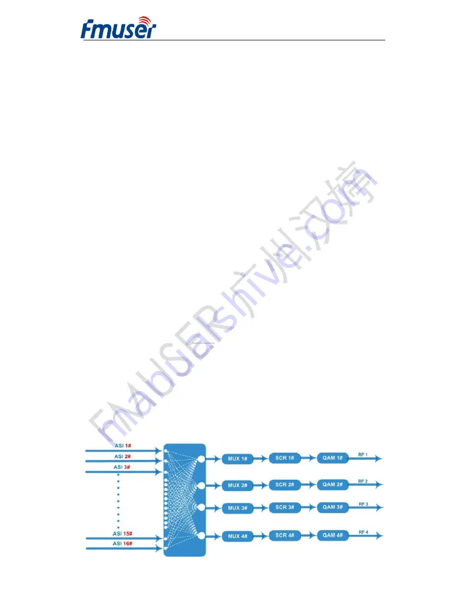
FUTV4443 is a cost effective integrated 4 in 1 QAM modulator supporting 

multiplexing and scrambling. This device supports maximum 16 ASI input, 

after 4 multiplexer and 4 scrambler process, then gives 4 carriers output (4 

adjacent frequency output by 1 RF port). It’s ideal for processing ASI input 

data from different devices and giving RF output by only one device. W ith 

its powerful function, it can reduce the operator business cost effectively. 

1.2 Features   

l

  Support 16 ASI input 

l

  Fully support EN300 429/ITU-T J.83A/B/C 

l

  Support PSI/SI editing and inserting 

l

  4 MUX,4 SCR, 4 QAM embedded 

l

  Support 4 simulcrypt CA 

l

  Support accurate PCR adjusting 

l

  4 Frequency output with excellent MER

40dB 

l

  Support 16/32/64/128/256QAM 


1.3 Principle chart 


Содержание FUTV4443

Страница 1: ...FMUSER INTERNATIONAL GROUP INC FUTV4443 4 in 1 Mux Scrambling QAM Modulator User s Manual NMS Version NMS 5 0 20 SW 0 22 HW 1 0 FMUSER International Group Inc...

Страница 2: ...ustration 3 2 1 Front Panel 3 2 2 Rear Panel 3 Chapter 3 Installation Guide 5 3 1 Acquisition check 5 3 2 Installation Preparation 5 Chapter 4 Operation 9 4 1 Operation 9 4 2 Main Interface 9 Chapter...

Страница 3: ...cy output by 1 RF port It s ideal for processing ASI input data from different devices and giving RF output by only one device With its powerful function it can reduce the operator business cost effec...

Страница 4: ...odulation Standard EN300 429 ITU T J 83A B C Symbol Rate 5 0 7 0Msps 1ksps stepping Constellation 16 32 64 128 256QAM FEC RS 204 188 RF Output Interface F typed output port for 4 carriers 75 impedance...

Страница 5: ...area All the indicators will light on when the 4 in 1 Mux Scrambling QAM works at current state 2 1 Front Panel 2 2 Rear Panel 1 ASI 1 16 IN Channel 1 16 ASI Input 2 Data No use temporarily just for f...

Страница 6: ...FMUSER INTERNATIONAL GROUP INC 4 42 6 Power Power Socket 7 Grounding Grounding Pole...

Страница 7: ...stall device please follow the below steps The details of installation will be described at the rest part of this chapter Users can also refer rear panel chart during the installation The main content...

Страница 8: ...ustainable 0 45 C short time installing air conditioning is recommended Relative humidity 20 80 sustainable 10 90 short time Pressure 86 105KPa Door window Installing rubber strip for sealing door gap...

Страница 9: ...s should connect to protective copper strip The grounding wire should be as short as possible and avoid circling The section of the conjunction between grounding wire and grounding strip should be equ...

Страница 10: ...in 1 Mux Scrambling QAM user should set the power switch to OFF 3 2 4 1 Signal wire connection of ASI IN The data input cable of 4 in 1 Mux Scrambling QAM is ASI cable while the output cable is the no...

Страница 11: ...fications or confirming the change after modification LEFT RIGHT To choose and set the parameters UP DOWN Modifying activated parameter or paging up down when parameter is inactivated LOCK Lock the sc...

Страница 12: ...the submenu 4 2 2 System Setting User can press ENTER to choose this item UP DOWN LEFT RIGHT to set the parameters The system displays following pages 4 2 2 1 Frequency After entering the submenu by...

Страница 13: ...onstellation to enter the QAM modulation mode selection ENTER to the specified setting The display shows as below There are five possible options 16QAM 32QAM 64QAM 128QAM and 256QAM User can press ENT...

Страница 14: ...Max_input_bitrate Symb_rate qam_bits 188 204 Max input bit rate the maximum effective inputting coding rate Symb rate the symbol rate Qam_bits the QAM bit when device works as current constellation u...

Страница 15: ...ere are two possible options 6MHz and 8MHz Therefore the frequency interval should be integral multiple of 6MHz 8MHz User can refer to the formula as below RF_BW symb_rate 1 roll_off RF_BW Frequency b...

Страница 16: ...e corresponding program The system displays following pages 4 2 4 Output Setting User can select Output setting in the main interface and then press ENETR to set the outputting parameters The display...

Страница 17: ...ing ENTER to enter into the attenuation setting in output 1 submenu repressing ENTER and moving UP DOWN LEFT RIGHT key to set the parameters The display shows as below The channel 1 output level atten...

Страница 18: ...ystem displays following pages Note The MAC address is according to the factory setting and it s unique Under the following submenus there are parameters which can be set manually user can press Up Do...

Страница 19: ...chooses 6 1 to load saved configuration the display shows as below When user chooses 6 2 to restore the device into factory configuration the display will automatically return to the main menu as belo...

Страница 20: ...language For example the version number of network management software 4 01E exe is 4 01 English version or place different versions of network management software to the same directory When the netwo...

Страница 21: ...node This software provides a powerful node operation function and the user can edit various parameters in the device tree for management and classification 5 2 3 Adding Frequency Point The Add Freq P...

Страница 22: ...oint in advance and then the dialog box of Add Equipment will pop up when user clicks Add Equipment item in the Edit pull down menu on the menu row or clicks right mouse key to pop up the short cut me...

Страница 23: ...ser should follow the steps as below l Inputting the device IP Address l Inputting the device Port Number l Inputting the Equipment Name l Choosing the connected equipment type in drop down list of Eq...

Страница 24: ...C IP address and device IP address should be in the same network For example the Device IP is 192 168 2 1 Submask is 255 255 255 0 So the NMS PC IP address should be 192 168 2 X 1 X 255 submask is 255...

Страница 25: ...tively user can also click the button on the toolbar to popup the save file dialog box which gives prompts to save all the device s parameters as binary files in the computer s hard disk Similarly use...

Страница 26: ...MS software 5 3 1 Mux Scrambler Setting In this field users can set and get the device inputting parameters 5 3 1 1 Mux 5 3 1 1 1 In this box all 16 inputting ports are displayed in the left box User...

Страница 27: ...42 5 3 1 1 2 Programs refresh input out User can select the program to be multiplexd and click the arrow to add it to the right box or user can delete the programs which have been multiplexed from th...

Страница 28: ...FMUSER INTERNATIONAL GROUP INC 26 42 5 3 1 1 3 Program Modification...

Страница 29: ...tween the 2 boxes then the modify interface pops out as shown above User can select the item to be modified and input new information in the corresponding box below To prosper the modification pls do...

Страница 30: ...FMUSER INTERNATIONAL GROUP INC 28 42 5 3 1 2 Scrambler Setting...

Страница 31: ...ate green means it works normally while red means communication error or no communication 4 User can set AC index ECM PID ECM ID of the current program 5 Output channel selecting 5 3 1 2 2 IPAddress T...

Страница 32: ...d to a new one 5 3 1 2 4 Output Bit rate This filed means the TOTAL bit rate of the current output 5 3 1 2 5 Users can refresh device parameter and get the current configuration 5 3 1 2 6 Users can su...

Страница 33: ...onfirm button to submit the current configuration and click the Cancel to quit the current operation 5 3 1 3 Transparent Transport Pass User can decide to bypass the inputting PID as needed in this in...

Страница 34: ...this interface user can input and check the source of PIDs in the first box the value of PIDs source in the second box and value of outputting PIDs which has been bypassed Clicking OK user can return...

Страница 35: ...network ID number NIT insertion Enable means the device will send the NIT table by itself and Disable means the NIT table cannot be sent out Pass through Multiplexing Pass through will enable all the...

Страница 36: ...5 3 1 5 NIT NIT Network Information Table NIT table is a very important table for describing the network and TS Users can set the parameters of the output NIT table on condition that the NIT Insertion...

Страница 37: ...ork name 5 3 1 5 2 Insertion private description This checkbox will allow user to insert the private descriptor into the output TS The private descriptor includes two parts One is descriptor tag and t...

Страница 38: ...when users select it and then users can edit the NIT table and output it and These two buttons can trigger a window to load save the saved NIT table file from to a file on local computer hard disk Use...

Страница 39: ...y means the centre frequency of TS output Therefore user can only set the start frequency from 48MHz to 968MHz if the bandwidth is 8M and from 48MHz to 976MHz if the bandwidth is 6MHz Out gain attenua...

Страница 40: ...FMUSER INTERNATIONAL GROUP INC 38 42 NOTE After completion of configration of all the parameters click Remote Save button on the toolbar to save the modifications to the device s flash...

Страница 41: ...5 C l Making sure good ventilation for the heat sink on the rear panel and other heat sink bores if necessary l Checking the input AC voltage within the power supply working range and the connection i...

Страница 42: ...FMUSER INTERNATIONAL GROUP INC 40 42 Chapter 7 Packing List l FUTV4443 4in1 Mux Scrambling QAM 1pc l User s manual 1pc l AC Power cord 1pc l Grounding wire 1pc l ASI wire 16pcs...

Отзывы: