background image

                                                  FMUSER INTERNATIONAL GROUP INC. 

广州市汉婷生物技术开发有限公司


8

 / 

57


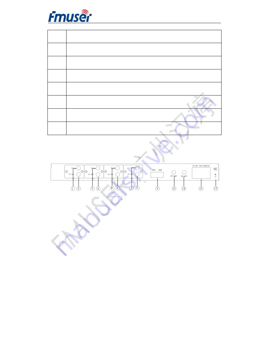
LOOP OUT 3: Loop Out Channel 3 

RF IN 4: RF In Channel 4 

LOOP OUT 4: Loop Out Channel 4 

Ethernet: DATA Port & NMS Port 

10 

RF Test: RF Test Interface 

11 

RF out: RF output interface   

12 

Power Socket 

13 

Grounding pole   


2.2.3 Rear Panel (DVB-S/S2 In)   


The rear panel description is same as 2.2.2 DVB-C in. 


Содержание FUTV4440B

Страница 1: ...FMUSER INTERNATIONAL GROUP INC 1 57 FUTV4440B 4 in 1 QAM Modulator User Manual Version 1 0 Date 2015 06 16 NMS Version 5 12 3 SW V1 04 HW V1 8 FMUSER International Group Inc...

Страница 2: ...DVB S DVB C DVB S2 signals by installing the relevant build in tuners or ASI input optional 6 Chapter 3 Installation Guide 9 3 1 Acquisition check 9 3 2 Installation Preparation 9 Chapter 4 Operation...

Страница 3: ...carrier has independent signal channel encoding and direct RF output Therefore the device is featured with excellent RF performance index It supports 4 channel ASI inputs 4 QAM J 83 A B C 4 DVB S tun...

Страница 4: ...TS packet l DVB S DVB S2 DVB C RF input optional l Support accurate PCR adjusting l Support five QAM constellation ITU T J 83A modes 16 32 64 128 256 QAM l Support QAM constellation ITU T J 83B ITU T...

Страница 5: ...32 64 128 256QAM FEC RS 204 188 RF Output Interface F type 75 impedance Frequency range 30 960 MHz 1khz stepping Output level 16dbm 0dbm per QAM carrier 0 5db stepping MER 40db ACLR 55 dBc System Supp...

Страница 6: ...4 in 1 QAM modulator can take various RF inputs of DVB S DVB C DVB S2 signals by installing the relevant build in tuners or ASI input optional 2 2 1 Rear Panel ASI In 1 LCD Display 2 Indicator Area PO...

Страница 7: ...ASI IN 4 ASI Input Channel 4 5 Ethernet DATA Port NMS Port 6 RF TEST RF Test Interface 7 RF OUT RF Out Interface 8 Power Power Socket 9 Grounding Grounding Pole 2 2 2 Rear Panel DVB C In 1 RF IN 1 RF...

Страница 8: ...3 7 RF IN 4 RF In Channel 4 8 LOOP OUT 4 Loop Out Channel 4 9 Ethernet DATA Port NMS Port 10 RF Test RF Test Interface 11 RF out RF output interface 12 Power Socket 13 Grounding pole 2 2 3 Rear Panel...

Страница 9: ...uner wire If any item is missing please inform local dealer 3 2 Installation Preparation When users install device please follow the below steps The details of installation will be described at the re...

Страница 10: ...temperature 5 40 C sustainable 0 45 C short time installing air conditioning is recommended Relative Humidity 20 80 sustainable 10 90 short time Pressure 86 105KPa Door window Installing rubber strip...

Страница 11: ...r well electric conducting and process for antirust 4 It is prohibited that users use other devices as part of grounding wire s electric circuit 3 2 3 1 Frame Grounding All the machine frames should c...

Страница 12: ...tive ground it should adopt independent way say sharing the same ground with other devices When the device adopts united way the grounding resistance should be less than 1 FCaution Before connecting p...

Страница 13: ...FMUSER INTERNATIONAL GROUP INC 13 57 ASI cable coaxial cable user owned Network cable user owned...

Страница 14: ...lue resuming previous setting Return to previous menu ENTER Activating the parameters which need modifications or confirming the change after modification LEFT RIGHT To choose and set the parameters U...

Страница 15: ...ws figure 1 and figure 2 After switching on the LCD will alternatively display the figure 1 and figure 2 User can press Lock key to enter into the main menu As display shown the first row is the outpu...

Страница 16: ...y to enter the main menu the LCD will display the following pages By pressing UP DOWN LEFT DOWN key to choose the specified menu item then pressing ENTER to enter the 1 System Setting 2 Channel Settin...

Страница 17: ...start frequency After entering the submenu by pressing ENTER key user can set the start frequency by moving the UP DOWN LEFT RIGHT key and then repressing ENTER to save The RF output range is from 48M...

Страница 18: ...ions are different according to the different modulate standard set in 1 2 J 83A DVB C 16QAM 32QAM 64QAM 128QAM and 256QAM J 83B 64QAM and 256QAM J 83C 64QAM and 256QAM User can press ENTER and move U...

Страница 19: ...n transport is limitary when the device works as different constellations and symbol rates User can refer to the formula as below Max_input_bitrate Symb_rate qam_bits 188 204 Max input bit rate the ma...

Страница 20: ...point bandwidth the symbol rate should not exceed 5 217Msps When users choose 8M as the frequency point bandwidth the symbol rate should not exceed 6 956Msps 4 2 2 5 Bandwidth After entering the subm...

Страница 21: ...s 6 956Msps to ensure the bandwidth for each channel no more than 6MHz 8MHz 4 2 2 6 RF Level Out Power General attenuation setting After entering the submenu by pressing ENTER key user can set the gen...

Страница 22: ...w 4 2 3 1 1 Output carrier User can decide whether to turn on the channel 1 s output carrier By pressing ENTER after selecting the Output Carrier moving the LEFT RIGHT key to set repressing ENTER to c...

Страница 23: ...level attenuation is from 0 16db in 0 5db step 4 2 3 1 3 NIT insertion By pressing ENTER to enter into the NIT Insertion in channel 1 submenu repressing ENTER key and moving LEFT RIGHT key to choose...

Страница 24: ...her to enable or disable the PID filtering function 4 2 3 2 Channel 2 DVB C In as an example User can choose channel 2 in the submenu by pressing ENTER and the display shows as below 4 2 3 2 1 Output...

Страница 25: ...is only for setting the frequency of DVB C signal 4 2 3 2 6 QAM modulation mode By pressing ENTER to select the modulation mode via the UP and DOWN button The optional mode is 16QAM 32QAM 64 QAM 128 Q...

Страница 26: ...3 in the submenu by pressing ENTER and the display shows as below 4 2 3 3 1 Output Carrier same as 4 2 3 1 1 4 2 3 3 2 Attenuation same as 4 2 3 1 2 4 2 3 3 3 NIT Insertion same as 4 2 3 1 3 4 2 3 3...

Страница 27: ...d to be demodulated 4 2 3 3 6 LNB Frequency By pressing ENTER to enter into the LNB Frequency in channel 3 submenus repressing ENTER key and moving LEFT RIGHT key to choose The display shows as below...

Страница 28: ...oltage By pressing ENTER to enter into the LNB Voltage in channel 3 submenus repressing ENTER key and moving LEFT RIGHT key to set The display shows as below By pressing Enter key the state will be ch...

Страница 29: ...lected state Note The submenu is only for setting whether to enable or disable the 22KHZ Switch of the DVB S signal needed to be demodulated 4 2 3 4 Channel4 DVB S2 IN as an example same as 4 2 3 3 Ch...

Страница 30: ...nter and Left Right to set the parameters The system displays following pages 4 2 5 Save configuration User can choose to save the current configured parameters by pressing ENTER key The system displa...

Страница 31: ...user chooses 5 1 to load saved configuration the display shows as below When user chooses 5 2 to restore the device into factory configuration the display will automatically return to the main menu a...

Страница 32: ...ation User can just copy Network Management Software X XXY exe to the specified directory X XX is version number Y represents language For example the version number of network management software 4 0...

Страница 33: ...g Confirm key after inputting user name and password Upon the inputs the software will verify them with database record automatically If both of them are correct the main interface will appear Both of...

Страница 34: ...e node tree in the left column by adding modifying and deleting the device node This software provides a powerful node operation function and the user can edit various parameters in the device tree fo...

Страница 35: ...wn menu on the menu row The device will confirm the given frequency while user clicks OK User can also click right mouse key to pop up the short cut menu in device tree or in the left blank column the...

Страница 36: ...7 5 2 4 Adding Equipment under Given Frequency Point User should choose the frequency point in advance and then the dialog box of Add Equipment will pop up when user clicks Add Equipment item in the E...

Страница 37: ...ATIONAL GROUP INC 37 57 5 2 5 Edit Equipment Interface User should follow the steps as below Choosing the connected equipment type in drop down list of Equipment Type by clicking the l Inputting the E...

Страница 38: ...5 2 7 Save Configuration After finishing all the parameters setting user can click button on the toolbar to save the modifications to the device s flash while user can also reload the saved parameters...

Страница 39: ...ad the stored binary file and set the device s parameters according to the loaded binary files 5 3 FUTV4440B 4in1 QAM Modulator Operation User can choose the 3340B 4 in 1 QAM in the device tree Set ma...

Страница 40: ...NC 40 57 5 3 1 Parameter 5 3 1 1 IN NOTE Parameters In Channel 1 2 3 4 The channel interface presents different content automatically according to the signal input ports see 5 3 1 1 1 5 3 1 1 4 5 3 1...

Страница 41: ...NAL GROUP INC 41 57 Program select Selecting the programs that needed to output PSI Parser Pressing this button to analyze the input programs 5 2 1 1 2 DVB C in Here taking channel 1 of DVB C tuner in...

Страница 42: ...Signal strength indicating the input signal intensity l Signal quality indicating the input signal quality l Program select Selecting the programs that needed to be outputted l PSI Parser Pressing th...

Страница 43: ...olarization here are 2 points for selecting V 13v and H 18v l Tuner 22 KHz User can decide whether to switch the tuner frequency by selecting ON OFF l LNB frequency User should check the tuner install...

Страница 44: ...Program select Selecting the programs that needed to be outputted l PSI Parser Pressing this button to analyze the input programs 5 3 1 1 4 DVB S2 In l The description of DVB S2 tuner input is the sam...

Страница 45: ...out gain are general parameters and effective for each channel 5 3 1 2 1 J 83 This item is for selecting the modulating standard this device supports J 83A DVB C J 83B and J 83C 5 3 1 2 1 Constellatio...

Страница 46: ...oints to the channel 1 s center frequency 5 3 1 2 6 Outgain refer to 4 2 2 5 Total output level attenuation User can see following description about start frequency The RF output frequency range is fr...

Страница 47: ...ONAL GROUP INC 47 57 5 3 2 Output carrier refer to 4 2 3 1 1 User can decide how many channels TS are being transported by selecting the checkbox and the channel selected will be closed The illustrati...

Страница 48: ...alue If the input bit rate is exceeding the over flow indicator will be light on 5 3 4 Effective bit rate User can also refer to the maximum bit rate formula and table The current setting is 64 QAM co...

Страница 49: ...ws as below Note For each channel its out gain equals to the general out gain circled by red line pluses the respective out gain circled by blue line For example the channel 1 out gain in above illust...

Страница 50: ...FMUSER INTERNATIONAL GROUP INC 50 57 5 3 6 2 MODE 2 5 3 6 3 MODE 3 5 3 6 4 MODE 4...

Страница 51: ...ur PID tables provided for each channel to filter mainly including PAT PMT SDT and NIT table User can choose to filter the original PID as needed by selecting the checkboxes left below or they can als...

Страница 52: ...parser to get the original data l clicking Psi edit to create new data l selecting the checkboxes in Parameters interface to confirm filtering l clicking set to make the insertion replacement effecti...

Страница 53: ...hould clicking this button before editing new table 5 3 8 5 Psi Edit Use can edit new PID data by entering the editor interface 5 3 9 NIT refer to 4 2 3 1 3 NIT Network Information Table NIT table is...

Страница 54: ...insert the private descriptor into the output TS The private descriptor includes two parts One is descriptor tag and the other is descriptor information Descriptor tag The descriptor tag is an 8 bit f...

Страница 55: ...fy button will trigger a modify window and allow user to modify the selected items in the NIT table 5 3 9 2 4 Delete The Delete button will remove the selected items in the NIT table 5 3 9 2 5 Clear T...

Страница 56: ...tion Measure l Installing the device at the place in which environment temperature between 0 to 45 C l Making sure good ventilation for the heat sink on the rear panel and other heat sink bores if nec...

Страница 57: ...cuit short l Device in damp environment l Device was suffered from physical damage l Longtime idle l After switching on and restoring to factory setting device still cannot work properly l Maintenance...

Отзывы: