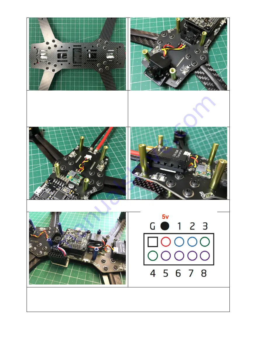
16.
The main frame plate should now be fixed
to the bottom of the drone to cover over the
ESCs. To secure it in place, use the M3x8mm
button head screws and washer for each, along
with a drop of thread lock.
17.
The next couple of stages install the FPV
equipment. Taking the FPV camera, stick it in
position using the supplied foam pad. Now cut
its wires to an appropriate length and solder
them to the PDB taking note of the labeled
connections (yellow is video and not labeled).
18.
The FPV transmitter is attached in the same way as the camera. Stick it to the PDB using the
supplied foam pad and also solder its wires to the VTX connections.
19.
The build is nearly complete, now you need to attach your radio receiver. A PWM breakout
cable is provide for connection to a standard receiver. The receiver connections are shown in the
diagram above with the channel order being: AIL (1), ELE (2), THR (3), RUD (4), AUX1..AUX4 (5-8).
Note that the top left pin is ground, and the pin to its right is the 5v supply for your receiver.
Содержание G-Force250
Страница 1: ...G Force250 FPV Racing Drone Kit...


