RUSKA 2413, 2417 & 2416
Users Manual
6-4
Failure Diagnoses
Some transformers have been known to fail at high pressure and to resume operation at a
lower one. Failure is usually traced to an opening in one of the windings.
If an instrument fails to display a difference in pressure as expected, a simple and quick
test will indicate if the cause is in the electronic circuit or in the differential transformer.
When the connecting cable is removed from the transducer, the meter in the control box
circuit should be capable of being brought to zero with the zero potentiometer. If this
condition is true, the problem may then lie in the transformer.
A resistance measurement of the windings will establish the condition of the windings.
The measurements may be made at the receptacle on the transducer as follows:
Table 6-2. Resistance Measurements for the Windings
Connection Winding
Approximate
Resistance (ohms)
D-C (Gnd)
Secondary
100
F-C Secondary
100
B-A (Gnd)
Primary
300-2000*
*A series resistor is sometimes added to the primary winding at the transducer for matching purposes. An
open primary should show infinite resistance.
In some instances, after a prolonged period of over-ranging pressure on the diaphragm in
the direction of a liquid medium, it is possible for the diaphragm to stick to the cavity
surface. With the diaphragm in this position, the cell displays the same symptoms as
those of a defective transformer. The resistance tests will indicate which of the conditions
exist. This condition may be encountered, for example, when making phase studies with
gases. Under this circumstance application of a small liquid overpressure against the
diaphragm with the intent of dislodging it will be unsuccessful. The area of the
diaphragm exposed to the pressurized liquid is so small that only a small, dislodging
force actually exist. If the pressure is increased with the expectation of results, the
diaphragm may break loose with a shock and disturb the core on the stem. The lodging
pressure should not exceed 4 or 5 atmospheres and should be left applied until the
diaphragm is released.
1.
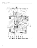
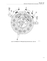
Remove the circular base, supporting legs, tie bolts (Symbol 27) and top cap (1) as
described in this section on replacement of the diaphragm. Take note of any solid
debris that may have accumulated on the floor of the exposed transformer chamber.
Every effort must be directed to prevent any of the particles from being washed into
the diaphragm cavity during exchange of the transformer.
2.
Pour the oil from the chamber. With tweezers, slide the plastic sleeves back from the
connections at the feed-thru terminal. While holding the cell semi-inverted — about
45o with bottom up — over a container, direct a stream of solvent (Freon TF or
mineral spirits) into the cavity and particularly around the feed-thru connections.
A 2 or 3 ounce plastic ear syringe is suitable for this purpose. The reason for
inverting the cell while flushing is to prevent any solid contaminants that may have
come to rest in the transformer chamber from being washed into the diaphragm
cavity. Do not disturb any of the wires while performing this operation.
Содержание RUSKA 2413
Страница 6: ...RUSKA 2413 2417 2416 Users Manual iv ...
Страница 8: ...RUSKA 2413 2417 2416 Users Manual vi ...
Страница 26: ...RUSKA 2413 2417 2416 Users Manual 6 6 ...
Страница 34: ...RUSKA 2413 2417 2416 Users Manual 8 2 ...
Страница 36: ...RUSKA 2413 2417 2416 Users Manual 9 2 ...


