Roofit.Solar Double Seam, Installation Manual
The "Roofit.Solar Double Seam" Installation Manual is a crucial resource for hassle-free installation of our groundbreaking solar product. Download this comprehensive manual for free from manualshive.com, ensuring a seamless setup process and optimizing the performance of our cutting-edge solar technology.
Share
Download


Reviews:
No comments
Related manuals for Double Seam

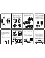
F-TPBR
Brand: NAPCO Pages: 8
XTouch Series: XTouch50
Brand: Xilica Audio Design Pages: 2

S-Class Excellent
Brand: Centrosolar Pages: 68

GOT3126T-832
Brand: AXIOMTEK Pages: 46

SolarFree 800C Supreme
Brand: Aquagarden Pages: 2

intelligent Touch Manager
Brand: Daikin Pages: 44

AFL-A-N270
Brand: IEI Technology Pages: 168

RNG-KIT-STCS100D-NC-U
Brand: Renogy Pages: 12

DFG-RS3
Brand: Omega Pages: 24

GOT3217WL-845-PCT
Brand: AXIOMTEK Pages: 44

39810
Brand: Sunforce Pages: 1

KronoMeet KT-1010SC
Brand: Kramer Pages: 2
KT-107
Brand: Kramer Pages: 41

PE-PLK-120WPX20A
Brand: Powereco Pages: 17

90-143
Brand: NEO TOOLS Pages: 13

Solargen PHOTOVOLTAIC
Brand: Baxi Pages: 32

5000 Series
Brand: OHAUS Pages: 60

60-924-3-C4TS
Brand: Interlogix Pages: 6


