


Calibration Manual
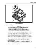
Verification Tests
17
OFF
A
mA
COM
V
1000V
30mA
FUSED
0.44A
(1A /30 sec)
FUSED
mA
mA
A
mA
OUTPUT 0-24mA
SOURCE SIMULATE
+
+
% STEP
COARSE
FINE
mV
V
V
OUTPUT
CAT
787
PROCESSMETER
MIN MAX
RANGE
HOLD
H
REL
Hz
UUT
5500A
POWER
I
O
0
•
1
2
3
4
5
6
7
8
9
ENTER
M
k
m
V
Hz
FIELD
EDIT
/
+
F
OPR
EARTH
SCOPE
BOOST
MENU
PREV
SHIFT
RESET
CE
SETUP
REF
NEW
TC
MEAS
¡F
µ
n
p
W
dBm
sec
¡C
A
MULT
x
DIV
÷
OUT
TRIG
5500A CALIBRATOR
20V PK
MAX
HI
LO
TC
TRIG
OUT
1000V
RMS
MAX
20V
RMS
MAX
1V PK
MAX
20V PK
MAX
NORMAL
AUX
SCOPE
V, ,
RTD
A, -SENSE,
AUX V
200V PK
MAX
STBY
(BLUE)
LT003F.EPS
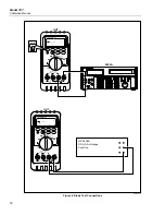
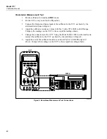
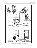
Figure 5. Current Measurement Test Connections
Checking the Diode Test Function
1.
Put the calibrator in Standby (
STBY
) mode.
2.
Put the UUT rotary switch in the
R
e
G
position.
3.
Press the BLUE button to select diode test (
G
)
.
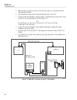
4.
Connect the calibrator to the
COM
and
z
terminals on the UUT as shown in
Figure 6.
5.
Apply 2.0 V dc from the calibrator.
6.
The UUT should read between 1.959 V and 2.041 V.
7.
Put the calibrator in Standby (
STBY
) mode; then disconnect the calibrator from the
UUT.
8.
Put the multimeter in the dc mA (autorange) function.
9.
Connect the current terminals of the multimeter to the
COM
and
z
terminals
on the UUT.
10.
The multimeter should read close to 0.2 mA. (There is no tolerance specification for
this current. This test just makes sure that the diode test current source is operating.)
Содержание ProcessMeter 787
Страница 2: ......
Страница 4: ...Model 787 Calibration Manual ii ...
Страница 6: ...Model 787 Calibration Manual iv ...
Страница 8: ...Model 787 Calibration Manual vi ...
Страница 40: ...Model 787 Calibration Manual 32 ...


