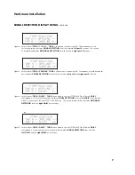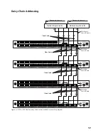
Figure 13. Example of a tap section removal
1. Remove the miniature 4-pin, male quick lock power supply connector from the
POWER
port of
the FTAP-x-2X8 Fiber Tap.
2. Remove the DRL460-6-6 control Y-cable DB9 lead from the
CONTROL
port of the Fiber Tap.
3. DO NOT DISTURB THE NETWORK FIBER CABLES. Remove
ONLY
the DRL408-2m SC to SC cables
(orange) for multi-mode or DRL438-2m SC to SC cables (yellow) for single-mode from the
TAP
and
DAISY
ports of the Fiber Tap.
4. Loosen the two rear panel thumbscrews, as shown in
Figure 12
, about 5 turns in a counter-
clockwise direction until they spring-free from the main chassis section threads. Apply gentle
but equal pressure to the thumbscrews to start the forward motion of the Fiber Tap section
and remove it from the rack enclosure as shown in
Figure 13
.
SWITCH SECTION REPLACEMENT
To reinstall the FTAP-x-2X8 Fiber Tap section into the rack enclosure, perform the FTAP-x-2X8
Fiber Tap Section Removal procedure in the reverse order of removal.
13
Switch Removal and Replacement

