SIGNAL DETECTION DISPLAY DETAIL
The signal detection built into the FTAP-x-2X8 Fiber Tap indicates the presence of a fiber optic signal,
determines the direction the signal is traveling, and displays a graphical representation of the signal
direction. The typical display described herein will be for a FTAP-x-2X8 Fiber Tap as shown in the
examples below.
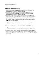
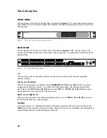
Figure 2. Connect the miniature 4-pin male quick lock power supply connector into the
POWER
port of the
FTAP-x-2X8 Fiber Tap and then plug the power supply into the external power source wall receptacle.
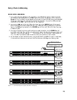
Shortly after powering up, an initialization message (i.e., “loading”) will be displayed.
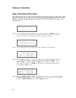
Figure 3. Next, the Fluke Networks logo will illuminate the display, indicating successful initialization.
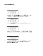
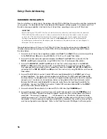
Figure 4. The scrolling graphic displays the FTAP-x-2X8 Fiber Tap model number (FTAP-SX50-2X8, FTAP-SX62-2X8
or FTAP-LX-2X8, depending on your configuration) and switch status (
TAP A
=
OFFLINE _ _
and
TAP B
=
OFFLINE _ _
).
TAP A
and
TAP B
are
OFFLINE
and all optical signals are ignored. The two
horizontal bars to the right of the
OFFLINE
port status indicates no optical signal is being processed
by either
TAP A
or
TAP B
data path.
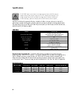
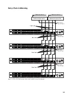
Figure 5. Switch status (
TAP B
=
CHAN #5
).
TAP B
is connected to channel port
5
. The first horizontal bar indicates
NO SIGNAL DETECTION
from the network
left port 5
receiver. The arrowhead on the second horizontal
bar indicates
SIGNAL DETECTION
from the network
right port 5
receiver.
6
Hardware Installation


