


HF170AEN_OS_v0501_04
Page 38
INDEX OF THIS MANUAL
actual settings
40
analog
flowrate min.
19
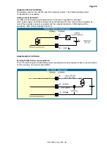
passive output.
29
tune / calibrate
19
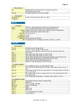
Backlight 30
battery life time
17
communication 30
family-specific variables
36
terminal connection
30
Configuration
10
Dimension enclosures
23, 24
display
function
16
display update
17
flowmeter 17
flowrate
decimals 14
decimals Span
14, 15
measuring unit
14
Span 14
Installation 22
IP classification
22
keys 7
level 8
alarm 9
alarm value
8
decimals 15
measuring unit
15
Span 15
low-battery 9
Low-battery alarm
9
main-function 11
maintenance 31
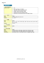
model 21
Operator level
8
password 21,
35
Problem solving
35
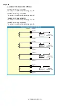
pulse output
27, 28
Sensor input
29
serial number
21
SETUP-level 10
subfunction 11
tagnumber 21
Technical specification
32
terminal connectors
27
version software
21
LIST OF FIGURES IN THIS MANUAL
Fig. 1: Typical application for the F170-A-OS. ..................................................................................... 5
Fig. 2: Control Panel. ............................................................................................................................ 7
Fig. 3: Example of display information during process. ........................................................................ 8
Fig. 4: Example display information during programming maximum level. .......................................... 8
Fig. 5: Example of low-battery alarm. ................................................................................................... 9
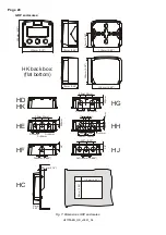
Fig. 6: Dimensions aluminum enclosures. .......................................................................................... 23
Fig. 7: Dimensions GRP enclosures. .................................................................................................. 24
Fig. 8: Grounding aluminum enclosure with type PM 115-230V AC. ................................................. 25
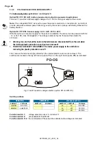
Fig. 9: switch position voltage selection (option PD and PD-OS). ..................................................... 26
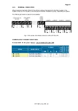
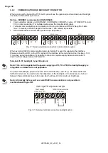
Fig. 10: Overview of terminal connectors of the F170-A-OS. ............................................................. 27
Fig. 11: Overview terminal connectors communication option. .......................................................... 30
Fig. 12: Overview terminal connectors backlight option. .................................................................... 30