


HF170AEN_OS_v0501_04
Page 26
4.4.2.
VOLTAGE SELECTION SENSOR SUPPLY
For Intrinsically Safe applications: read chapter 5.
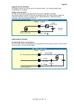
Option PB / PC / PX (AP) - battery powered and output loop-powered applications:
Terminal 11 provides a limited supply voltage of 3.2 V DC for the signal output of the sensor.
Note:
This voltage MAY NOT be used to power the sensors electronics, converters etc, as it will not
provide adequate sustained power! All energy used by the sensors pick-up will directly influence the
battery life-time.
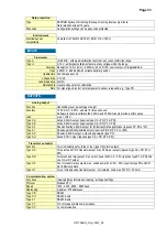
Option PD / PF / PM: Sensor supply: 3.2V - 8.2V - 12V or 24 V:
With this option, a real power supply for the sensor is available. The sensor can be powered with 8.2
- 12 or 24 V DC (max. 50mA@24V). The voltage is selected by the three switches inside the
enclosure.
Warning: be sure that all the leads to the terminals are disconnected from the unit when
the internal plastic protection cover has been removed!
HIGH VOLTAGE 400V !! DISCONNECT the mains power supply to the unit before
removing the plastic protection cover !!!
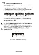
First, remove the terminal strip(s) after which the internal plastic cover can be removed. The
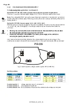
switches are located in the top left corner (option PD) or on the right hand (option PM) as indicated:
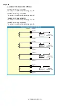
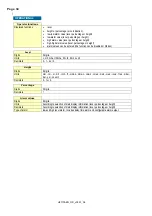
Fig. 9: switch position voltage selection (option PD and PD-OS).
Switch positions
SENSOR
A
SENSOR
B
VOLTAGE SELECTION
SWITCH
1
VOLTAGE
SWITCH
2
VOLTAGE
SWITCH
3
SWITCH
4
VOLTAGE
internal
3.2 V DC
on
on
8.2 V DC
external switch
3+4
on
off 12
V
DC
off
off 23
V
DC
Function switch 1:
voltage selection sensor A - terminal 11.
Function switch 2:
not available for this Model.
Function switch 3+4:
the combination of these switches determine the voltage as indicated.
on
off
4
3
1
INT EXT
1
INT EXT
on
off
PD-OS