Fluidwell F170-A-OS Скачать руководство пользователя страница 32


HF170AEN_OS_v0501_04


Page  32

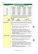
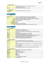
APPENDIX A:  TECHNICAL SPECIFICATION 


Display 


Type 

High intensity reflective numeric and alphanumeric LCD, UV-resistant. 

Digits 

Seven 17mm (0.67") and eleven 8mm (0.31"). Various symbols and measuring units. 

Refresh rate 

User definable: 8 times/sec - 30 secs. 

Option ZB 

Transflective LCD with green LED backlight. Good readings in full sunlight and darkness. 
Note: only available for safe area applications.  

Power requirements: 12-24V DC + 10% or type PD, PF, PM. Power consumption max. 1 Watt. 


Enclosures


General 


Control Keys 

Painting 

Die-cast aluminum or GRP (Glassfibre Reinforced Polyamide) enclosure with Polycarbonate 

window, silicone and EPDM gaskets. UV stabilized and flame retardant material. 

Three industrial micro-switch keys. UV-resistant silicone keypad. 
Aluminum enclosure only: UV-resistant 2-component industrial painting. 

Panel-mount enclosures 

Classification 

Panel cut-out 

Type HC 

Type HB 

Dimensions: 130 x 120 x 60mm (5.10" x 4.72" x 2.38") – LxHxD.  
IP65 / NEMA4X 

115 x 98mm (4.53" x 3.86") LxH. 

GRP panel-mount enclosure 

Aluminum panel-mount enclosure 

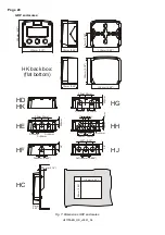
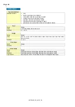
Field/wall-mount enclosures 

Classification 

Aluminum enclosures 

Type HA 

Type HM 

Type HN 

Type HO 

Type HP 

Type HT 

Type HU 

Type HV 

Type HZ  

GRP enclosures 

Type HD 

Type HE 

Type HF 

Type HG 

Type HJ 

Type HH 

Type HK 

ABS enclosure 

Type HS 

Dimensions: 130 x 120 x 75mm (5.10” x 4.72” x 2.95”) – LxHxD. 

IP67 / NEMA4X 

 
Drilling: 2x PG9 – 1x M20. 

Drilling: 2x M16 – 1x M20. 

Drilling: 1x M20. 

Drilling: 2x M20. 
Drilling: 6x M12. 

Drilling: 1x ½”NPT. 

Drilling: 3x ½”NPT. 

Drilling: 4x M20 
No drilling. 


No drilling. 

Drilling: 2x 16mm (0.63”) – 1x 20mm (0.78”). 

Drilling: 1x 22mm (0.87”). 
Drilling: 2x 20mm (0.78”). 

Drilling: 3x 22mm (0.87”). 

Drilling: 6x 12mm (0.47”). 

Flat bottom - no drilling. 
 

Silicone free ABS enclosure with EPDM and PE gaskets. UV-resistant polyester keypad.  

(no drilling) 


Operating temperature


Operational 

-40°C to +80°C (-40°F to +176°F) 


Power supply 

Type PD 

8-24V AC / DC + 10%. Power consumption max. 10 Watt.  
Intrinsically safe: 16-30V DC; power consumption max. 0.75 Watt. 


Sensor excitation 

Type PD 

1.2 - 3.2 - 8.2 - 12 and 24V DC - max. 50mA@24V DC 


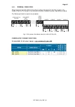
Terminal connections 

Type: 

Removable plug-in terminal strip. Wire max. 1.5mm2 and 2.5mm2 (Type PM / PF) 


GENERAL 

Содержание F170-A-OS

Страница 1: ...VEL ALARMS Signal input sensor 0 4 20mA Signal outputs 4 20mA ref level Alarm outputs maximum four level alarms Options Modbus communication F Series Field mounted indicators for safe and hazardous ar...

Страница 2: ...a battery is present in this product it should be disposed of separately The separate collection and recycling of your waste equipment will help to conserve natural resources and ensure that it is rec...

Страница 3: ...es which if not performed correctly may lead to personal injury a safety hazard or destruction of the F170 A OS or connected instruments A caution indicates actions or procedures which if not performe...

Страница 4: ...14 1 Level 14 2 Height 15 3 Alarm 16 4 Display 16 5 Power management 17 6 Sensor 17 7 Analog output 19 8 Relay output 20 9 Communication optional 20 A Others 21 4 Installation 22 4 1 General directio...

Страница 5: ...ties with ABS or aluminum enclosures for harsh industrial surroundings ability to process all types of level signals transmitting possibilities with analog alarm relay and communication option outputs...

Страница 6: ...e transflective LCD with all kinds of symbols and digits to display measuring units status information trend indication and key word messages Options Following options are available isolated or active...

Страница 7: ...of the F170 A OS This instruction is meant for users operators 2 2 CONTROL PANEL The following keys are available Fig 2 Control Panel Functions of the keys This key is used to program and save new val...

Страница 8: ...the measuring unit will be displayed or the percentage or height When is shown then the level value is too high to be displayed The arrows indicate the increase decrease of the level trend After press...

Страница 9: ...that the level is outside it s range without an immediate alarm Low battery alarm When the battery voltage drops it must be replaced At first low battery will flash but as soon as it is displayed con...

Страница 10: ...are to be observed Ensure that the measuring system is correctly wired up according to the wiring diagrams The housing may only be opened by trained personnel Take careful notice of the Safety rules i...

Страница 11: ...nique number which is displayed below the word SETUP at the bottom of the display The number is a combination of two figures The first figure indicates the function group and the second figure the fun...

Страница 12: ...When data is altered but ENTER is not pressed then the alteration can still be cancelled by waiting for 20 seconds or by pressing ENTER for three seconds the PROG procedure will be left automatically...

Страница 13: ...DELAY ALARM HIGH 0 1 999 9 seconds 39 DELAY ALARM high high 0 1 999 9 seconds 4 DISPLAY 41 ALARM SET operator setup hidden off 42 FUNCTION level level height level percentage height height percentage...

Страница 14: ...level is determined on the basis of the selected measurement unit at 20mA Enter the span in whole numbers decimals are set with SETUP 14 The more accurate the span the more accurate the functioning of...

Страница 15: ...e selected 00000 1111 1 2222 22 SPAN 23 With the span the sensor signal is converted to a height The span for height is determined on the basis of the selected measurement unit at 20mA The more accura...

Страница 16: ...generated as long as the level is higher as this value With value 999999 this function is disabled ALARM VALUE HIGH HIGH 35 The high high alarm is set with this setting An alarm will be generated as...

Страница 17: ...modes operational or shelf After shelf has been selected the unit can be stored for several years it will not process the signal the display is switched off but all settings and totals are stored In t...

Страница 18: ...lue at flow zero Warning be very sure that the offered signal is correct before the calibration is executed as this function has major influences on the accuracy of the system After pressing PROG thre...

Страница 19: ...set for level setup 1 or height setup 2 When percentage is chosen they reflect and one decimal Note that the units cannot be displayed CUT OFF 75 A low level cut off can be set as percentage over the...

Страница 20: ...be entered Based on the options order the F170 A OS will have 2 3 or 4 alarm outputs Note If the unit is Intrinsically Safe it will have two alarm outputs If option OS relay board is supplied it will...

Страница 21: ...This window shows the model number of this product F170 A VERSION SOFTWARE A2 This window shows the software version running in the F170 A OS SERIAL NUMBER A3 This window shows the unique serial numbe...

Страница 22: ...l contact is no longer assured when the housing cover is removed or the panel cabinet has been opened danger from electrical shock The housing may only be opened by trained personnel Take careful noti...

Страница 23: ...0mm 30mm 22 5mm M20 x 1 5 M16 x 1 5 M16 x 1 5 30mm 30mm 22 50mm M20 x 1 5 22 5mm M20 x 1 5 M20 x 1 5 25mm 25mm 22 5mm 1 2 NPT 0 9 3x 1 2 NPT 0 12 0 12 0 9 HA HM HN HO HP HT HU 6 x M12 12mm 12mm 24mm 2...

Страница 24: ...ck box flat bottom HE HF HG HH D 12mm 12mm 12mm 24mm 24mm 36mm 36mm 14mm 17mm 22 5mm 30mm 30mm D 16mm D 20mm 0 9 D 22mm 0 866 22 5mm 25mm 25mm D 20mm D 20mm D 16mm HC 75 mm 2 95 118 mm 4 65 104 mm 4 0...

Страница 25: ...ue to impact or friction sparks between the enclosure and iron steel is excluded Do ground the aluminum enclosure properly as indicated if the F170 A OS has been supplied with the 115 230V AC power su...

Страница 26: ...sure Warning be sure that all the leads to the terminals are disconnected from the unit when the internal plastic protection cover has been removed HIGH VOLTAGE 400V DISCONNECT the mains power supply...

Страница 27: ...tors installed may vary depending on options The following terminal connectors are available Fig 10 Overview of terminal connectors of the F170 A OS POWER SUPPLY CONNECTOR OPTIONS Terminal GND 01 02 p...

Страница 28: ...his output is an alarm output according setup 81 Terminal 12 13 relay output R2 This output is an alarm output according setup 82 Terminal 14 15 relay output R3 This output is an alarm output accordin...

Страница 29: ...el is available as standard A DC power supply should be connected to terminal 08 and 09 the current is then regulated by unit When a power supply is connected but the output is disabled a 3 5mA signal...

Страница 30: ...e to this terminal and set it active 12V If no active signal is available it is possible to connect a separte supply between terminals 26 and 27 with a voltage between 8V and 24V Terminal 26 31 backli...

Страница 31: ...oes not require special maintenance unless it is used in low temperature applications or surroundings with high humidity above 90 annual mean It is customers responsibility to take all precautions to...

Страница 32: ...5 NEMA4X 115 x 98mm 4 53 x 3 86 LxH GRP panel mount enclosure Aluminum panel mount enclosure Field wall mount enclosures Classification Aluminum enclosures Type HA Type HM Type HN Type HO Type HP Type...

Страница 33: ...1 kOhm Type AA Active 4 20mA output requires type OA PD PF or PM Type AB Active 0 20mA output requires type OA PD PF or PM Type AF Passive floating 4 20mA output for Intrinsically Safe applications r...

Страница 34: ...idden Level Digits 6 digits Units L m3 GAL USGAL KG lb bbl no unit Decimals 0 1 2 or 3 Height Digits 6 digits Units mm cm m mtr inch ft mmwk mmwc cmwk cmwc mwk mwc inwc ftwc mbar bar psi no unit Decim...

Страница 35: ...nown If the password is not 1234 there is only one possibility left call your supplier ALARM When the alarm flag starts to blink an internal alarm condition has occurred Press the select button severa...

Страница 36: ...n 7 gal 8 bbl 9 lb 10 cf 11 rev revolutions for RPM 12 none 50 32h decimals 1 0 1 51 33h span 3 1 9 999 999 S 0000001 up to S 0000009 is allowed when decs 6 VAR54 54 36h decimals span 1 0 6 ALARMS 234...

Страница 37: ...50 116 74h maximum rate 3 0 9999999 unit time decimals acc var48 50 119 77h cut off percentage 1 0 99 steps of 0 1 120 78h tune minimum rate 2 0 9999 122 7Ah tune maximum rate 2 0 9999 99 63h filter...

Страница 38: ...blem solving 35 pulse output 27 28 Sensor input 29 serial number 21 SETUP level 10 subfunction 11 tagnumber 21 Technical specification 32 terminal connectors 27 version software 21 LIST OF FIGURES IN...

Страница 39: ...IGURATION SETTINGS SETTING DEFAULT DATE DATE 1 LEVEL Enter your settings here 11 unit L 12 decimals 0000000 13 span 000001 14 decimals span 0 15 off set 0 2 HEIGHT 21 unit m 22 decimals 000000 23 span...

Страница 40: ...rat low 0 4mA default 65 calibrat high 20mA default 7 ANALOG OUTPUT 71 output disabled 72 input level 73 min flowrate 4 mA 0000000 74 max flowrate 20mA 9999999 75 cut off percentage 0 0 76 tune min 4m...

Отзывы: