


HF170AEN_OS_v0501_04
Page 10
3. CONFIGURATION
3.1. INTRODUCTION
This and the following chapters are exclusively meant for electricians and non-operators. In these,
an extensive description of all software settings and hardware connections are provided.
Mounting, electrical installation, start-up and maintenance of the instrument may only
be carried out by trained personnel authorized by the operator of the facility. Personnel
must read and understand this Operating Manual before carrying out its instructions.
The F170-A-OS may only be operated by personnel who are authorized and trained by
the operator of the facility. All instructions in this manual are to be observed.
Ensure that the measuring system is correctly wired up according to the wiring
diagrams. The housing may only be opened by trained personnel.
Take careful notice of the " Safety rules, instructions and precautionary measures " in
the front of this manual.
3.2. PROGRAMMING
SETUP-LEVEL
3.2.1. GENERAL
Configuration of the F170-A-OS is done at
SETUP
-level.
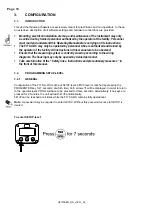
SETUP
-level is reached by pressing the
PROG/ENTER key for 7 seconds; at which time, both arrows
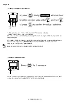
will be displayed. In order to return
to the operator level, PROG will have to be pressed for three seconds. Alternatively, if no keys are
pressed for 2 minutes, the unit will exit
SETUP
automatically.
SETUP
can be reached at all times while the F170-A-OS remains fully operational.
Note:
A password may be required to enter SETUP. Without this password access to SETUP is
denied.
To enter SETUP-level: