FW_F113A_v1901_02_EN.docx
Page 36
Fig. 29: F113-A-AP-(CT)-IB-OT-PD-XI - External power supply - IIC
Страница 1: ...r 0 4 20mA Signal outputs 0 4 20mA ref flow rate and pulse ref total Alarm outputs maximum four flowrate alarms Options Intrinsically safe Modbus communication external reset and backlight F Series Fi...
Страница 2: ...to the general waste system or into a landfill At the end of its life equipment shall be disposed of according to the local regulations regarding waste of the electrical and the electronic equipment P...
Страница 3: ...A or connected instruments A caution indicates actions or procedures which if not performed correctly may lead to personal injury or incorrect functioning of the F113 A or connected instruments A not...
Страница 4: ...ion of SETUP menu A Others 16 4 Installation 17 4 1 General directions 17 4 2 Installation surrounding conditions 17 4 3 Dimensions Enclosure 18 4 4 Installing the hardware 20 4 4 1 General installati...
Страница 5: ...med Linear 0 4 20mA or 0 10V analog output to represent the actual flow rate as programmed The 0 4 20mA or 0 10V signal limits can be tuned Fig 1 Typical application Configuration The F113 A is design...
Страница 6: ...shown information depends on the settings which are made in the setup menu The signal from the connected sensor is processed by the F113 A in the background independent from the selected display refre...
Страница 7: ...go to the next number The PROGRAM indicator blinks continuously You can select the required alarm threshold The 0 zero in front of the number will not show when the setting is saved The alarm is only...
Страница 8: ...ossible to prevent access to the SETUP menu with a password A password may be required to enter the SETUP menu Without this password access to SETUP is denied 3 1 HOW TO PROGRAM THE F113 A The setup m...
Страница 9: ...and the setting UNIT When you do not want to save the change wait for approximately 20 seconds or press and hold the PROG ENTER key for approximately 3 seconds Action Result Remark 1 Momentarily press...
Страница 10: ...0 full brightness 44 bl alarm off on flash 5 POWER MANAGEMENT 51 LCD new fast 1 sec 3 sec 15 sec 30 sec off 52 battery mode operational shelf 6 FLOWMETER 61 formula interpolation square root 62 filter...
Страница 11: ...unit is m3 The rate per second is 2 481 3 60 is 41 355 L sec This is 0 041355 m3 sec which is the span Enter for the span 041355 and for the span decimals 6 When you recalculate and enter a new span t...
Страница 12: ...HI 34 This setting is used to activate the related alarm condition and to set the threshold value for a this flow alarm The setting 0 0 disables this alarm ALARM HH 35 This setting is used to activate...
Страница 13: ...ed In this mode power consumption is extremely low To wake up the F113 A again press the SELECT key two times 3 1 7 EXPLANATION OF SETUP MENU 6 FLOWMETER FORMULA 61 The F113 A can process the 0 4 20mA...
Страница 14: ...r pressing enter CAL SET will be shown as soon as the calibration is completed From that moment the analog value must be less than the calibrated value for a reliable measurement DEFAULT with this set...
Страница 15: ...less actual representation of the flow rate can be obtained The filter principal is based on three input values the filter level 01 99 the last calculated flow rate and the last average value The high...
Страница 16: ...rors in the communication safety To maintain a secure operation automation and control it is the sole responsibility of the owner to install and manage the appropriate safety measures to protect the n...
Страница 17: ...SURROUNDING CONDITIONS Take the relevant IP classification of the enclosure into account see identification plate Even an enclosure rated for IP67 TYPE 4 X should NEVER be exposed to strongly varying...
Страница 18: ...0 6 deeper rear cover 75 mm 2 95 130 mm 5 12 112 mm 4 40 120mm 4 72 M20 x 1 5 PG9 PG9 30mm 30mm M20 x 1 5 M16 x 1 5 M16 x 1 5 30mm 30mm M20 x 1 5 M20 x 1 5 M20 x 1 5 25mm 25mm 1 2 NPT 0 9 3x 1 2 NPT 0...
Страница 19: ...36 120 mm 4 72 HD HK HK back box flat bottom HE HF HG HH D 12mm 12mm 12mm 24mm 24mm 36mm 36mm 14mm 17mm 22 5mm 30mm 30mm D 16mm D 20mm 0 9 D 22mm 0 866 22 5mm 25mm 25mm D 20mm D 20mm D 16mm HC 75 mm...
Страница 20: ...non metallic enclosure could invalidate isolation 4 4 1 GENERAL INSTALLATION GUIDELINES The F113 A that came with a power module type PM 110V 230V AC or type PD PF with an option OR the relays can han...
Страница 21: ...nd a washer is used torque 2 Nm The metal front cover is connected to the Protective Earth by the mounting screws with serrated washers To ground the panel mounted unit the PE conductor must be connec...
Страница 22: ...0V AC Type OR 8 24V AC Type OR 8 30V DC 4 4 4 ALUMINUM ENCLOSURE PANEL MOUNTED The PE connection The PE connection is made with one of the mounting screws that attaches the front panel to the panel Ty...
Страница 23: ...STIC GRP ENCLOSURE The PE connection The F113 A in a GRP enclosure meets the requirements of class 2 double insulated Therefore the incoming PE wire is terminated with an insulating end cap Type PM 11...
Страница 24: ...onnectors Standard configuration and options 4 4 7 SENSOR SUPPLY For type PB PC PX AP There is no real sensor supply out available Only a limited power supply is available This power supply MAY NOT be...
Страница 25: ...wer supply in 15 24V AC 20 30V DC Switch location typical Sensor Vout selection Sensor supply out A 1 2 3 4 int off off Not suitable for analog sensors 3V DC 1mA ext on on off on off off 8 2V DC 8Vin...
Страница 26: ...nal connections Active output typical Type OR A mechanical relay output flow rate alarm output or pulse output is available with this option Max switch power 240V 0 5A per output Requires power supply...
Страница 27: ...on these terminals Max driving capacity 1000 Ohm 24VDC Requires power supply type PD PF PM Fig 13 Terminal connections 4 20mA analog output typical Type AB An active 0 20mA signal proportional to the...
Страница 28: ...Terminal connections Active 0 10V analog output typical Terminal 09 11 Type A Flowmeter input general The F113 A requires a 0 4 20mA flowmeter signal which will be processed 4 times a second with a 1...
Страница 29: ...20 Terminal connections External reset typical Terminal 15 16 alarm pulse output R3 This output is designed as a fast output with a maximum frequency of 500Hz For the use with a mechanical relay and...
Страница 30: ...the RS232 communication option terminal 27 is used for supplying the interface Please connect the DTR or the RTS signal of the interface to this terminal and set it active 12V If no active signal is...
Страница 31: ...ron steel is excluded For EPL Da the ambient temperature Ta shall not exceed 50 C Safety instructions When two or more active Intrinsically safe circuits are connected to the indicator in order to pre...
Страница 32: ...ear of production This information can be looked up in the setup menu Others Fig 23 Example serial number typical Label information pulse input type F1xx XI inside and outside the enclosure Fig 24 Lab...
Страница 33: ...it supply connected to terminals 7 and 8 type AP The maximum values for any of those circuits are those as defined for group IIB IIIC No other active external intrinsically safe circuits may be connec...
Страница 34: ...main external power supply is connected The sensor supply voltage is fixed 8 2V DC Set the sensor supply 1 Make the F113 A safe If applicable mind the battery power 2 Open the F113 A and carefully rem...
Страница 35: ...FW_F113A_v1901_02_EN docx Page 35 5 3 CONFIGURATION EXAMPLES INTRINSICALLY SAFE APPLICATIONS Fig 28 F113 A AP CT IB OT PC PD XI Battery powered IIB IIC IIIC...
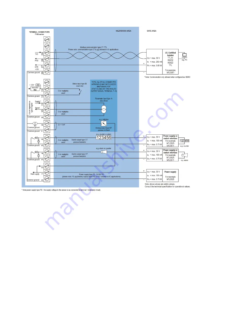
Страница 36: ...FW_F113A_v1901_02_EN docx Page 36 Fig 29 F113 A AP CT IB OT PD XI External power supply IIC...
Страница 37: ...y with the utmost care to prevent a short circuit and damage 4 Do not recharge crush disassemble incinerate heat above its rated temperature or expose the contents to water 5 Dispose of the battery in...
Страница 38: ...that the function is disabled if not in use or else it will have a major influence on the battery life time Display update fast display update uses significantly more power Pulse output and communicat...
Страница 39: ...Type HJ Type HH Type HK Dimensions 130 x 120 x 75mm 5 10 x 4 72 x 2 95 3 54 WxHxD IP67 TYPE 4 X where H turns to HS for stainless enclosures e g HA HSA Drilling 2x PG9 1x M20 Drilling 2x NPT Drilling...
Страница 40: ...th variable decimal position Update time Four times a second Relationship Linear and square root calculation Note External power to sensor is required e g Type PD Voltage drop 2 5 Volt 15BReset Type I...
Страница 41: ...ow rate alarm values can be entered this function can be disabled 20BTotal Digits 7 digits Units L m3 kg lb GAL USGAL bbl no unit Decimals 0000000 111111 1 22222 22 3333 333 Note total can be reset to...
Страница 42: ...vice able to recognize the selected amount Flow rate displays 0 zero while there is flow total is counting Check are the Span and time unit correct The password is unknown If the password is not 1234...
Страница 43: ...dditional information regarding using your Modbus device please read our General Modbus Communication Protocol and Modbus troubleshooting guide that are available through our website or your distribut...
Страница 44: ...d 70 h 0x046 40071 flow zero 1 r w uint16 0 ignore 1 default 2 no relay d 234 h 0x0EA 40235 alarm value low low 2 r w uint32 0 9999999 d 240 h 0x0F0 40241 alarm value low 2 r w uint32 0 9999999 d 243...
Страница 45: ...0 h 0x078 40121 tune minimum rate 1 R W uint16 0 9999 d 122 h 0x07A 40123 tune maximum rate 1 R W uInt16 0 9999 d 127 h 0x07F 40128 filter 1 R W uint16 1 99 PDU ADDRESS REGISTER VARIABLE RELAYS NO REG...
Страница 46: ...9 d 160 h 0x0A0 40161 model suffix 1 R char Representation ASCII character d 162 h 0x0A2 40163 firmware version 2 R uint32 0 999999 Representation nn nn nn d 165 h 0x0A5 40166 serial no 2 R uint32 0 9...
Страница 47: ...FW_F113A_v1901_02_EN docx Page 47 APPENDIX D DECLARATION OF CONFORMITY...
Страница 48: ...g 8 Overview of terminal connectors Standard configuration and options 24 Fig 9 Sensor supply voltage Switch setting 25 Fig 10 Terminal connections Active output typical 26 Fig 11 Terminal connections...
Страница 49: ...FW_F113A_v1901_02_EN docx Page 49 NOTES...
Страница 50: ...delay hi 0 0 39 delay hh 0 0 4 DISPLAY 41 function total 42 alarm set operate 43 light 100 44 bl alarm off 5 POWER MANAGEMENT 51 LCD new 1 sec 52 battery mode operate 6 FLOWMETER 61 formula interpola...
Страница 51: ...FW_F113A_v1901_02_EN docx Page 51 95 parity none A OTHERS A1 model F113 A A2 software version A3 serial no A4 password 0000 A5 tag nr 0000000...
Страница 52: ...Fluidwell B V PO box 6 Voltaweg 23 Website www fluidwell com 5460 AA Veghel 5466 AZ Veghel Find your nearest representative www fluidwell com representatives the Netherlands the Netherlands 2021 Fluid...