Limitorque L120-85 Installation, Operation and Maintenance FCD LMENIM1202-03-A4 – 06/15
20
4.4.1 Basic Theory of Operation
As torque is developed by the actuator, the Worm moves axially and causes compression on the Spring Pack Assembly (components of
the Worm Shaft Assembly (piece 15)). The Spring Pack Assembly is calibrated so that a given amount of spring compression equates to a
given amount of output torque. Axial Worm Shaft Assembly movement causes the Torque Switch Shaft (piece 300-13) to move, therefore
engaging the Torque Switch measurement device. Once the Torque Switch is properly set, it measures valve, or other equipment, torque
input in the ELECTRIC or MANUAL operating modes.
4.4.2 Setting the Torque Switch
a
CAUTION:
Installing or adjusting the Torque Switch with the actuator in a loaded condition will result in loss of torque protection.
Before adjusting or installing the Torque Switch, place the actuator in MANUAL mode and turn the Handwheel in the direction
necessary to release the torque load on the Worm Shaft Assembly.
NOTE:
If Torque Switch replacement is required, be sure to use an L120-85 Torque Switch rather than replacing with an L120-10 thru
40 Torque Switch. The L120-85 Torque Switch Torque Arm is rotated 10° from the position of the Torque Arm on the L120-10 thru 40
Torque Switch (the red dot on the Torque Switch Shaft indicates an L120-85 Torque Switch).
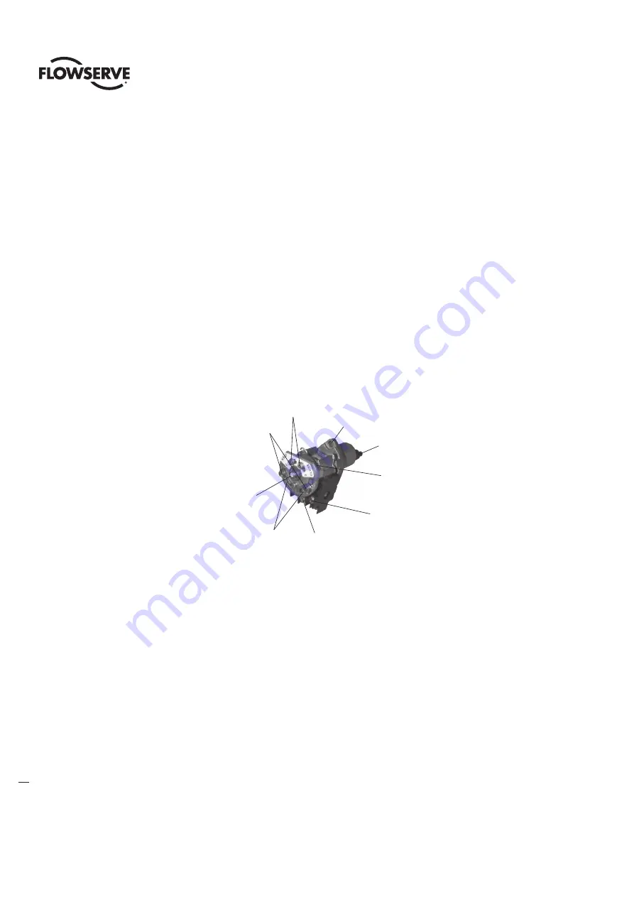
Figure 11: Torque Switch Components
ID Limiter
Plate (not shown)
#300-4 Torque Switch
Adjustment
Screws
#300-8 Balancing
Screws
Mounting
Screw Hole
Torque Arm
Red dot indicates
L120-85 Torque Switch
Typical OPEN
contact assembly
(18 & 18C)
#300-2 & 300-3
Index Arm
Typical CLOSE
contact assembly
(17 & 17C)
1. Turn all power to the actuator OFF.
2. Loosen the Torque Switch Adjustment Screws (piece 300-4) on the OPEN or CLOSED side of the Torque Switch.
3. Move Index Arm (piece 300-2 or piece 300-3) to desired torque setting. The higher number indicates an increased torque and/or thrust
output requirement.
4. Tighten the Torque Switch Adjustment Screws (piece 300-4).
5. Turn power ON and operate the valve electrically to seat the valve or other device and to ensure tight shut-off.
4.4.3 Balancing the Torque Switch
If the Torque Switch has been removed from the actuator or if you are installing a new Torque Switch, it must be rebalanced using the
following procedure:


