


Maintenance 13
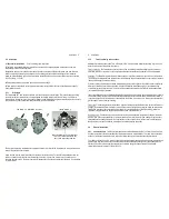
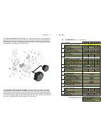
4.4 Inspection
(refer Exploded View)
Inspect O-rings for damage, chemical attack, deformity or any form of
deterioration.
Remove, inspect and clean the rotors, also check that the magnets have not been chemically attacked. Check the
measuring chamber for damage or scoring & redress if necessary, the rotor shafts should NOT be loose or able to
be rotated.
4.5 Re-assembly of meter
(refer Exploded View)
When
r
e-installing the rotors all four magnets MUST be
visible when both rotors are in place. Both rotors will only engage correctly if fitted precisely at an orientation of 90
degrees to each other. Rotate the rotors slowly by hand to ensure they are correctly fitted at the same time check
the rotor shafts & rotor bearings for wear.
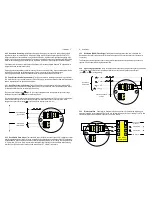
Fit the O-ring into the groove and assemble the two parts of the meter, the body & cap align with a location pin.
Fit the body cap screws (5) and tighten in a star sequence then torque in the same sequence to 3.5 Nm. This
sequence and procedure ensures the meter bodies are assembled correctly and evenly. Fit the pulse output board,
terminal cover or instrument as appropriate.
14 Fault finding
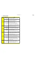
5.0 Fault Finding
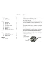
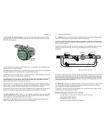
Pulse meters have two distinct sections: the mechanical wetted section housing the rotors
and the electrical section housing the pulse output board.
Meters fitted with integral instruments have these two sections plus the instrument.
The aim of fault finding is to trace the source of the fault to one of these sections.
If a fault is traced to an instrument section, refer to the relevant instruction manual.
Below are basic fault finding steps. Also refer to Trouble Shooting Guide on following page.
Step 1
-
Check application, installation and set up.
Refer to Mechanical Installation section for installation and application factors that may effect the meter operation
including pulsation and air entrainment or incorrect meter selection including incorrect flow rate, temperature and
pressure or materials compatibility. Refer to Electrical Installation for correct wiring.
Step 2
-
Check for blockages.
The most common cause of fault/unsatisfactory meter operation, particularly for new or altered installations, is due
to blockage within the system or meter caused by foreign particles such as weld slag, sealing tape or compound,
rust, etc.
Step 3
-
Ensure flow is present.
No flow or lower than normal minimum flow may be attributed to a blocked strainer, jammed or damaged rotors
within the flowmeter, malfunctioning pump, closed valves or low liquid level in feeder tank.
Step 4
-
Ensure oval gears within meter are rotating.
Rotation of the oval gears can be heard by holding a screw driver blade to the meter body and pressing the handle
hard against the ear lobe. If necessary test the meter with the flow turned off and turned on to familiarize yourself
with the audible rotation signature.
Step 5
-
Ensure pulses are being generated during flowing conditions.
A multimeter is often not fast enough to distinguish the pulse train from the reed switch or Hall Effect sensor. An
oscilloscope will allow you to view the output pulse train. When viewing the Hall effect sensor pulse ensure a pull
up resistor is installed between the pulse output and the supply voltage (refer electrical installation).
Step 6
-
Confirm Instrument Operation.
If an associated instrument is connected to the flowmeter confirm its operation by simulating a pulse input onto the
flow input terminals. In most instances a contact closure on the flow input terminals is an adequate simulation.