

Maintenance 11
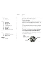
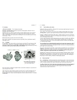
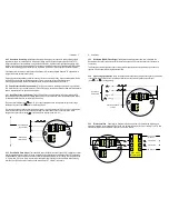
4.1 Disassembly of Pulse meter
(Refer Exploded View)
If required to gain access to the meter terminals and
pulse output board, undo the 4 cap screws (10), remove the terminal cover (9) carefully to avoid putting strain on
the terminal connections. The pulse output board (6) can now be accessed and removed if necessary (screws 7).
If required to gain access to the oval geared rotors undo the 8 body screws (5), carefully pry the meter body apart
avoiding misplacing or damaging the O-ring (3) and rotors (2).
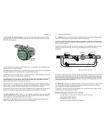
4.2 Dissassembly of meters fitted with an Instrument
If the meter is fitted with an integral instrument the
instrument display assembly must be removed if required to gain access to the instrument terminal connections,
instrument battery or pulse output board. This is achieved by undoing the bezel screws and separating the display
assembly from its base. Do not stress or damage the wires that connect the display assembly to the meter output.
Take care not to misplace or damage O-ring(s).The pulse output board can now be accessed. To remove the pulse
output board, first undo the screws that fix the instrument base to the flowmeter.
12 Maintenance
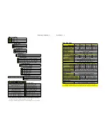
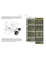
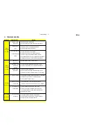
4.3 SPARE PARTS
(refer to exploded view)
Item Description
OM025
OM040
OM050
1
Body assembly with rotor shafts
Part No.
aluminum
1401096
1401094
1401092
stainless steel
1401097
1401093
2
Rotor assembly set
aluminum bearings
1424071
1424111
1424099
stainless steel bearings
1424092
1424125
1524011
3
Body O-ring
(size BS153)
(size BS245)
(size BS253)
viton
( standard )
13031531
13032451
13032531
teflon
13031533
13032453
13032533
4
Meter cap
aluminum with M20 conduit entry
1302047
1302160
1302088
aluminum with 1/2" NP T conduit entry
1302164
1302161
1302167
stainless with M20 conduit entry
1302165
1302166
1306025
stainless with 1/2" NP T conduit entry
1302059
1302162
1306029
5
Cap screw
(M6 x 20)
(M10 x 25)
(M10 x 25)
stainless & aluminum bodies
130816103 130810104 130810104
6
Pulse output board
standard pulse board
1412033
1412055
1412034
quadrature pulse board
1412039
1412040
1412040
7
Output board screw
M3 x 4 slot head
130803101
8
Terminal cover O-ring
suit std. stainless cover
(BS132)
13031321
suit E xd aluminum cover
(BS032)
13030321
9
Terminal cover
IP66/67 standard cover
(SS)
1306030
E xd explosionproof cover
(alum.)
1306020-E X
10 Terminal cover screw
M5 x 16
130805101
11 Flange portion O-ring
(size BS123)
(size BS136)
(size BS140)
viton
13031231
13031361
13031401
teflon
13031233
13031363
13031403
12 Flange portion screw
(M8 x 25)
(M10 x 30)
(M10 x 30)
socket head
130808103 130810104 130810105
13 Flange portion
refer diagram opposite
Recommended spare parts :
Item 2 rotor assembly set
Item 3 body O-ring
Item 6 pulse output board