Flomec OM025 Скачать руководство пользователя страница 5


                Installation    7 


2.2.2     Hazardous area wiring

  Intrinsically safe wiring including using the reed switch pulse output as simple 

apparatus, wiring to an Intrinsically Safe Instrument or wiring to the Exd explosionproof option( Exd IIB T4/T6 ) 
wiring techniques must be undertaken in accordance with the rules, regulations and requirements applying to the 
territory in which the meter is being installed. The meters should only be connected by qualified staff, the qualified 
staff must have knowledge of protection classes, regulations & provisions for the apparatus in hazardous areas. 
 
If the flowmeter is fitted with an intrinsically safe instrument refer to the appropriate manual & I.S. supplement for 
wiring of the instrument inputs and outputs. 
 
Earthing lugs are located within the terminal housing cover and on the meter body.


Use a separate earth within the 

cable making sure that the earth conductor does not come in contact with the cable shield / screen. 
Use only high temperature cable at the flowmeter when the process temperature exceeds 85

º

C. 


2.3     Pulse Output selection for pulse meters


 Two types of output are available on each meter, open collector 

from Hall Effect sensors or reed switch contact. Each output type is linearly proportional to volumetric flow and each 
pulse is representative of an equal volume of liquid. 


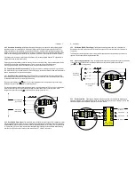
2.3.1    Hall Effect Sensor Pulse Output


The Hall Effect Sensor is a solid state 3 wire device providing a NPN 

open collector output. It requires a dc voltage between 5~24Vdc to operate and is the recommended pulse output 
for powered installations such as local or remote batching.


The pulse output between signal        and -0V is a voltage square wave with the high level being the dc voltage 
available at the open collector       and the low level being -0V.


The receiving instrument must incorporate a pull up resistor 

( typically greater than 10K ohms in most instruments ) 

which ties the


open collector to the available dc voltage level when the Hall sensor is not energized. When 

energized the


open collector output        is pulled to ground through the emitter (-0V). 


2.3.2     Reed Switch Pulse Output  

The reed switch output is a two wire normally open SPST voltage free contact 

ideal for installations without power or for use in hazardous area locations when Intrinsically Safe (I.S.) philosophy 
is adopted. 

Note:

  when using the reed switch output the liquid temperature must not change at a rate greater than 

10ºC per minute (50ºF per minute).


In general the reed switch life will exceed 2 billion actuations when switching 

less than 5Vdc @10mA as is the case when combined with the RT, EB or BT instruments. 


8      Installation  


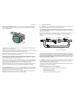
2.3.3     Quadrature (QUAD) Pulse Output  

The diagrams below apply when the meter is fitted with the 

Quadrature pulse output option 

(two Hall Effect sensors arranged to give separate outputs out of phase with 

one another).  


The Quadrature output is typically suited to custody transfer applications where signal integrity verification is 
required, it is also used for metering bi-directional flow.  


2.3.4


Signal integrity verification  

Many fiscal transactions require the primary measuring device 

(flowmeter)


to have Quadrature outputs in order to detect any difference in the number of pulses from each input  
(

 from

            &            ) during delivery.


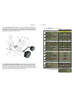
2.3.5     Bi-directional flow   

Combining the Quadrature feature and model PD1 pulse discriminator module 

produces  forward &  reverse outputs both of which may be integrated to provide a “net” reading. The RT12 flow 
rate totaliser will take both output & will perform the “net” flow function.   


phase shift between 

outputs 

Quadrature 

Pulse Output 

common 

to  

1 & 2

VDC 

+

 0V

QUAD 

NPN  HALL             EFFECT


REED Sw. 


VDC 

+

 0V 

QUAD 

NPN  HALL             EFFECT


REED Sw. 


Hall Effect NPN  

open collector 

Reed Switch 

contact closure 

VDC 

+

 0V 

-

QUAD 

NPN  HALL             EFFECT


REED Sw. 


PD1 Pulse 

Discriminator 

10 

8~24Vdc 

0V ground 

-

Reverse flow 

Forward flow 

Содержание OM025

Страница 1: ...w flomec com au USA 916 Belcher Drive Pelham AL 35124 USA Tel 1 205 378 1050 Fax 1 205 685 3001 Email customerservice trimecus com Website www trimecus com Distributed by Each meter has been calibrated on mineral oil and will contain a small amount of oil residue The oil used is Castrol Diesel Calibration Fluid 4113 product code 055830 Medium capacity positive displacement flowmeters OVAL GEAR SEE...

Страница 2: ...otalisers rate totalisers or batch controllers These instruments also have monitoring and control output options including 4 20mA scaled pulse flowrate alarms and batch control logic preset metering If your flowmeter is fitted or supplied with an instrument please also refer to the relevant instrument instruction manual These flowmeters can be installed within hazardous areas by using the reed swi...

Страница 3: ...en collector phased outputs 4 dc 2 stage batch controller OM040 OM050 accum reset totals pulse output IECEX ATEX approved IECEX ATEX approved IECEX ATEX approved Specifications Model prefix OM015 OM025 OM040 OM050 Nominal size inches 15mm 1 2 25mm 1 40mm 11 2 50mm 2 Flowrange litres min 1 40 10 150 15 250 30 450 Flowrange USGM 0 26 10 6 2 6 40 4 66 8 120 Accuracy 3cp Repeatability Temperature rang...

Страница 4: ...nd air entrapment which can result in erroneous readings or damage the meter on start up Process or safety critical meters should be installed in a by pass section of pipe with isolation valves to enable the meter to be isolated and serviced as required A by pass installation also allows purging of the system during commissioning see Commissioning The meter must be appropriately rated and is typic...

Страница 5: ...stor typically greater than 10K ohms in most instruments which ties the open collector to the available dc voltage level when the Hall sensor is not energized When energized the open collector output is pulled to ground through the emitter 0V 2 3 2 Reed Switch Pulse Output The reed switch output is a two wire normally open SPST voltage free contact ideal for installations without power or for use ...

Страница 6: ...ill have the relevant calibration factor entered into the program of the instrument Please refer to relevant instrument manual for programming details 10 Commissioning Maintenance 3 0 Commissioning Once the meter has been mechanically and electrically installed in accordance with this and any other relevant instrument manual s the meter is ready for commissioning The meter must NOT be run until th...

Страница 7: ...embly with rotor shafts Part No aluminum 1401096 1401094 1401092 stainless steel 1401097 1401093 2 Rotor assembly set aluminum rotors bearings 1424071 1424111 1424099 stainless steel rotors bearings 1424092 1424125 1524011 3 Body O ring size BS153 size BS245 size BS253 viton standard 13031531 13032451 13032531 teflon 13031533 13032453 13032533 4 Meter cap aluminum with M20 conduit entry 1302047 13...

Страница 8: ...tep 1 Check application installation and set up Refer to Mechanical Installation section for installation and application factors that may effect the meter operation including pulsation and air entrainment or incorrect meter selection including incorrect flow rate temperature and pressure or materials compatibility Refer to Electrical Installation for correct wiring Step 2 Check for blockages The ...

Страница 9: ...rminations wires for continuity 1 Rotors fouled 1 Check that rounded teeth are towards base of chamber 2 Check for obstruction due to foreign particles 3 Clean repair or replace rotors 2 1 See instructions for reassembly of meter with particular emphisis on positioning of rotors magnets 3 1 Check terminal connections solder joints 2 Ensure dc voltage is available at Vdc 0v and receiving instrument...

Отзывы: