

Installation 5
2.0 Installation
2.1 Mechanical Installation
Prior to installing the meter check :
#
The fluid is compatible with the meter materials of construction using appropriate information such as fluid
compatibility charts and site experience.
#
Application and process conditions are compatible with the meter specifications. Minimum and max. flows are
within the meter specified range including any in-situ cleaning processes. When metering viscous liquids the
maximum allowable flow may need to be reduced to ensure the pressure drop across the meter does not exceed
100 kPa
(1 Barg, 15 PSIG).
#
Process temperature and pressure does not exceed meter ratings.
#
The meter is not exposed to process temperatures and pressures that will cause the liquid medium to gasify
(flash) within the meter.
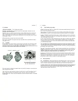
2.1.1
Orientation
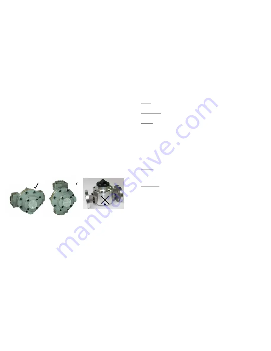
The flowmeter MUST be mounted so that the rotor shafts are in a horizontal plane. This is achieved by mounting
the meter so that the terminal cover or integral instrument display, whichever is fitted, is facing in a horizontal
direction. Note the terminal cover or instrument display can be rotated in 90 degree increments to provide access to
the electrical entry and to allow the display orientation to suit the installation.
The meter will operate in the alternative orientation, however, it is likely its life & performance will be reduced as a
result of the gravity pull on the rotors.
Liquid can flow into the meter from either a horizontal or vertical direction. For vertical flow installations the most
common orientation is for the liquid to rise through the meter
(i.e. travel from bottom to top
) to assist in air or
entrained gas elimination. The meter operation is independent of the liquid flow direction thus there is no markings
for inlet or outlet.
6 Installation
2.1.2
Flow Conditioning and Locations
Strainer :
It is recommended to INSTALL a 100mesh
(150 micron)
strainer immediately upstream of (prior to) the
meter. Strainers are available from the factory.
Flow conditioning :
The flowmeter does not require any flow conditioning, therefore straight pipe runs before or
after the meter are not required. If required, the pipe size about the meter can be altered to suit the installation.
Locations :
The flowmeter is preferred to be fitted upstream of any flow control and/or shut off valve, this prevents
free discharge from the meter and minimizes the risk of drainage and air entrapment which can result in erroneous
readings or damage the meter on start up.
Process or safety critical meters should be installed in a by-pass section of pipe with isolation valves to enable the
meter to be isolated and serviced as required. A by-pass installation also allows purging of the system during
commissioning
(see Commissioning)
.The meter must be appropriately rated and is typically located downstream
(on the discharge side)
of the pump.
If mounted outdoors ensure a suitable watertight gland or plug is used to seal any open electrical entries. In humid
environments take precautions to avoid condensation build up within the electrical and/or instrument enclosure. It
is good wiring practice for conduits to be connected from the bottom of an entry port, in this way condensation will
gravitate away from any terminal housing.
Fluid state :
Fluid entering the meter must remain a liquid at all times so protect the meter to avoid solidification or
gelling of the metered medium. If meters are to be trace heated or jacketed in any way the maximum temperature
rating of the meter must not be exceeded. Size the meter to avoid gasification of volatiles
(flashing)
within the
liquid due to the pressure drop experienced within the system or within the meter.
Hydraulic shock :
If pressure surges or hydraulic shock of any kind is possible, the system upstream of the meter
must be fitted with a surge suppressor or pressure relief valve to protect the meter from damage. High frequency
flow pulsations can damage the meter. Such pulsations can be caused by the injection profile in diesel engines.
Most pulsations are removed with the installation of a suitable pulsation dampener.
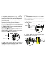
2.2
Electrical Installation
2.2.1 Instrument Cable
Twisted pair low capacitance shielded instrument cable 7 x 0.3mm
(0.5mm2)
should
be used for electrical connection between the flowmeter and remote instrumentation. The cable screen should be
earthed at the readout instrument only to protect the transmitted signal from mutual inductive interference.
The cable should not be run in a common conduit or parallel with power and high inductive load carrying cables as
power surges may induce erroneous noise transients onto the transmitted pulse signal or cause damage to the
electronics. Run the cable in separate conduit or with other low energy instrument cables. The maximum
transmission distance is typically 1000m
(3300 Ft).
I N C O R R E C T
When installed incorrectly the weight
of the rotors will bear down on the
base of the measuring chamber.
C O R R E C T O R I E N T A T I O N S