background image


Technical Guide 


CN-IC1-12


Title

:


i-Controller Visograph Navigation REV.201.05


EXTERNAL   


 36 


                      1-5JULY2021 

VAV Status 


Figure 1012. VAV I/O Status screen  


Demand Control Ventilation (DCV) 


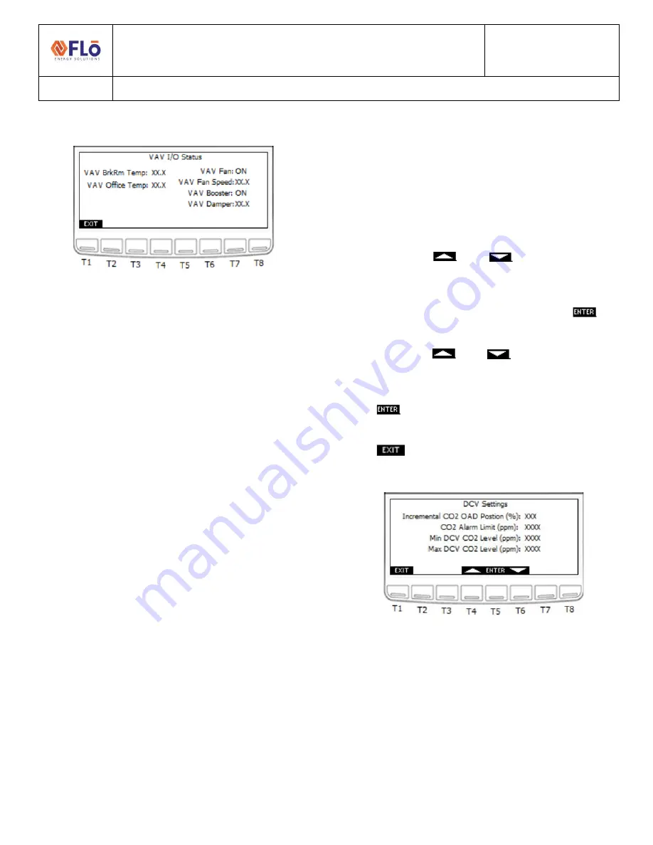
The  “DCV  Settings”  screen  is 

used  to  set  ventilation 

parameters  for  units  equipped  with  a  CO2  Sensor.  The 
beginning ventilation CO2 level, the max ventilation CO2 
level, and alarm parameter can be adjusted in this screen. 
To  adjust  the  CO2  ventilation  parameters,  perform  the 
following steps: 
 

1.


Using  the 

  and 

buttons  (T4  and  T6, 

respectively) navigate to the value that you wish to 
change. 


2.


Once the value is highlighted, press the 

 (T5) 

button and the value should blink. 


3.


Using  the 

  and 

buttons  increase  and 

decrease the value as desired. 


4.


Once the desired value has been reached press the 

 button to set the value. 


5.


Once all changes have been completed, press the 

  (T1)  to  return  to  the  Field  Tech  Options 

Menu. 


Figure 1023. DCV Settings screen


T1: Go to FT Menu 
T4: Increase Value 
T5: Enter 
T6: Decrease Value 

Содержание CN-IC1-12

Страница 1: ...Technical Guide CN IC1 12 Title i Controller VisographNavigation REV 201 05 EXTERNAL 1 1 5JULY2021 Flō i Controller Visograph Navigation for Version 201 05 ...

Страница 2: ...istory 18 Alarm Resets 18 Sensor Status 19 Network Information 20 Modbus Network 20 BACnet Network 20 Network Options 21 Field Tech Menu 22 Sensor Offsets 23 Pressure Sensors Offsets 24 VAV Offsets 24 Test Mode Descriptions 24 System Test Modes 25 Water Cooled Condenser 26 Chilled Water Unit 26 Air Balancing 26 Compressor Test Mode 26 Damper Test Mode 27 Condenser Fan Test Mode 27 Heat Test Mode 2...

Страница 3: ...s the Master controller All set point and schedule changes are to be made at the BMS Changes can be made on the i Controller but are temporary and will be overwritten by the BMS To make a temporary setting change perform the following steps 1 Unplug the RS485 Connector from the i Controller 2 Wait at least 90 seconds until the BMS Status on the Network Info screen on the Visograph reads Offline 3 ...

Страница 4: ...d Parameter File Message Figure 3 Version Information screen T2 Go to Overrides T8 Go to Main Menu File Descriptions These are the base files used for the firmware and controller parameters 1 ISaGRAF Version The version of the base program inside the i Controller This field should match the CRM field Revision for a given unit 2 VisoGraph Version The version of the screens shown on the Visograph 3 ...

Страница 5: ...in Menu T1 Go to Schedule T2 Go to Set Points T3 Go to Status T4 Go to Alarms T5 Go to Network Info T8 Go to Logo screen Schedules A schedule is used to activate deactivate an event on a specified day time To create a scheduled event use the arrow and enter keys to select the day of the week of the occurrence Select the occupied or unoccupied period and enter the hours and minutes for the event NO...

Страница 6: ...tion screens The Set Points option should only be used if operation set points are not being communicated to the Flō i Controller from a Building Management System BMS If the Flō i Controller is connected to a BMS over Modbus the set points shown on this screen will be automatically updated with the set points entered in the BMS The VAV Set Points will only appear if VAV controls are connected to ...

Страница 7: ...e 8 Occupied Set Points screen 1 T1 Go to Main Menu T4 Scroll Up Increase Value T5 Enter Select and Set Value T6 Scroll Down Decrease Value T7 Go to Previous Page T8 Go to Next Page Figure 9 Unoccupied Set Points screen 2 Figure 10 VAV Power Exhaust Fan Set Points screen 3 Zone Thermostat Control Units configured to use 2 Stage zone thermostats have the internal heating and cooling setpoints disab...

Страница 8: ...r if optional equipment is present 7 Energy Meter View current power consumption If Equipped Figure 13 System Status screen T1 Go to Main Menu T2 Go to Temperature Status T3 Go to Compressor Status T4 Go to Operation Mode T5 Go to Condenser Status T6 Go to Heat Status T7 Go to Optional Equipment Status T8 Go to Energy Meter Temperature Status There are 2 temperature status screens that display the...

Страница 9: ...compressors equipped in the unit The Suction Pressure Status will only appear if Compressor 2 is a digital scroll compressor when 4 compressors are present Compressor Status screens 3 and 4 will only be displayed when the unit is equipped with a third and fourth compressor Use the T7 and T8 buttons to navigate between the two Compressor Status pages The second Compressor Status page is only availa...

Страница 10: ...per mode during dehumidification or cooling call o High Dis Press Alarm Activated when the suction pressure increases above the upper pressure limit 500PSI o Suct Trans Fail Activated when the suction transducer reading is out of range o Dis Trans Fail Activated when the discharge transducer is out of range o Gradual Shutdown Activated when the discharge pressure of a digital compressor is above t...

Страница 11: ...us screen in place of the Compressor status screen Figure 21 System Status screen Figure 22 Chilled Water Status screen Figure 23 Chilled Water Status screen 2 Water Source Heat Pump WSHP When the unit is a WSHP the Suction Pressure Setpoint will be replaced Discharge Pressure Setpoint while the unit is heating operation Figure 24 WSHP Compressor Status while in Heating ...

Страница 12: ...l a value from 0 100 5 Compressor Capacity Total compressor capacity will display a value from 0 100 6 Heat Capacity Total heat capacity will display a value from 0 100 7 Reheat Reclaim Status Reheat or Reclaim Stage 1 ON or OFF when the coil is activated and deactivated 8 Reheat Reclaim 2 Status Reheat or Reclaim Stage 1 ON or OFF when the coil is activated and deactivated 9 Pre Heat Status If th...

Страница 13: ...nfo describes the condenser fan sequence and operation Figure 29 Condenser Info screen T1 Go to Condenser Status Menu Optional Equipment Status To view current status of optional connected equipment press T7 from the System Status Menu Optional equipment includes VAV zones ERV wheels Power Exhaust or Zone thermostat inputs Status will only appear if optional equipment is present Figure 30 Optional...

Страница 14: ...e ON or OFF If modulate heat is being used the value will be 0 100 5 VAV Damper VAV Damper position for associated zone Value will be 0 100 The VAV Status screen displays state of VAV inputs and outputs Figure 31 VAV Status screen T1 Go to Status Menu ERV Status From the System Status Menu press the T7 button to enter the Optional Equipment Status Menu page and then T3 for ERV Status page The ERV ...

Страница 15: ...he Zone Thermostat Status screen shows the input status of the 2 stage zone thermostat Figure 34 Zone Thermostat Status screen T1 Go to Optional Equipment Menu Energy Meter Status When the unit is equipped to monitor energy conception the Energy Meter Status will display the unit consumption and power factor Figure 35 Energy Meter Status screen T1 Go to Status Menu 1 Real Energy kWh Displays the R...

Страница 16: ...be replaced 2 Fan Status Alarm activated when a fan fail occurs 3 Overflow Alarm Alarm activated when a smoke detection signal is sent from the space This alarm will cause the unit to shut down 4 Phase Loss Alarm Alarm activated when improper voltage is supplied to the unit This alarm will cause the unit to shut down 5 Smoke Det Alarm Alarm activated when a smoke detection signal is sent from the ...

Страница 17: ...mit varies per mode during dehumidification or cooling call o Low Suct Press Activated when the suction pressure decreases below the lower pressure limit 80PSI o High Dis Press Alarm Activated when the suction pressure increases above the upper pressure limit 500PSI o OK Compressor is running properly o Comp Low Suction Trip Activated when a compressor s suction pressure drops below the safety lim...

Страница 18: ...erform the following steps 1 Using the and buttons T4 and T6 respectively ensure that the OFF value is highlighted 2 Press the T5 button and the value should blink 3 Using the and buttons increase and decrease the value until ON appears 4 Once the desired value has been reached press the button to set the value 5 Once the value has been set to ON the fan fail alarm has been reset and the fan is re...

Страница 19: ...igate between the two Sensor Status pages The Outdoor Humidity and CO2 sensors on the first page are optional and will not appear on the screen if these options are not included on the unit There are three Sensor Status screens Screen 3 is only visible if the unit contains VAV a hydronic heating coil a second space Temp or a 2nd Dehum Probe Figure 42 Sensor Status screen 1 T1 Go to Alarms Menu T7 ...

Страница 20: ... network this screen displays the Modbus address configurable and the Modbus baud rate To change the Modbus address 1 Using the and buttons T4 and T6 respectively navigate to the value that you wish to change 2 Once the value is highlighted press the T5 button and the value should blink 3 Using the and buttons increase and decrease the value as desired 4 Once the desired value has been reached pre...

Страница 21: ...hted press the T5 button and the value should blink 3 Using the and buttons increase and decrease the value as desired 4 Once the desired value has been reached press the button to set the value 5 Use the T7 and T8 buttons to navigate to the date and time screen 6 Repeat steps 1 4 until all desired values have been updated 7 Once all changes have been completed press the T1 button to return to the...

Страница 22: ...rt cooling heating occupancy mode and gas pressure check 3 Sensor Settings Set limits for dew point sensors suction transducers and discharge transducers 4 Set Damper Positions and Exhaust Interlocks Set the Outdoor damper operating percentage and damper percent increases for any available exhaust fan interlocks 5 Current Damper Positions View the positions of the outdoor return and bypass dampers...

Страница 23: ...e pressure transducers will only appear if the Flō unit has more than two compressors And the VAV sensor offsets will only appear if the unit is connected to a VAV zone Next to each offset is the actual sensor reading including the offset To adjust the sensor offset 1 Using the and buttons T4 and T6 navigate and highlight the next to the sensor you wish to adjust 2 Once the value is highlighted pr...

Страница 24: ...s allows for the total airflow requirements to be set with the VFD The Outdoor Return and Bypass are adjustable via the Override Val if necessary Toggle Supply Fan Balance Completed to YES when completed OAD Balance Mode When turned ON the Outdoor Air Damper will open to its default operating position the Return Air Damper will be set to 65 and the Bypass Damper will be set to 30 This allows the t...

Страница 25: ...System Tests Menu T3 Go to Operational Tests Menu T4 Go to Feature Tests Menu T5 Go to Sensor Verification T6 Go to Clear All Test Modes System Test Modes System Test modes are used to evaluate physical unit components System tests include Air Balancing Heat Exchanger Compressors Condenser Fans and Dampers System test modes will time out after 30 minutes Figure 60 System Test Modes screen T1 Go to...

Страница 26: ...e of Compressors From this screen the user will be able to perform various override functions Figure 63 Chilled Water Overrides screen Air Balancing Air Balancing Mode aids the air balancer in the balancing process Refer to AF IC1 01 i Controller Air Balancing Mode for additional instructions Figure 64 Air Balance Mode screen T1 Go to System Test Menu T4 Scroll Up Increase Value T5 Enter Select an...

Страница 27: ...ration NOTE Some condenser fans are wired directly to compressor outputs this mode will activate the associated compressor to activate the chosen condenser fan Figure 67 Condenser Fan Test Mode screen Heat Test Mode Figure 68 Heat Test Modes screen Full capacity heat test mode turns ON all heating stages Staged heat test mode is used to turn ON each stage of heat individually Reheat Reclaim Test E...

Страница 28: ...ication When activated the space temperature and humidity will be overridden to 72 F and 70 resulting in a dew point reading of 70 F To ensure the compressors initiate the suction pressure will be overridden to 200PSI if ambient conditions are above compressor lockout conditions Comfort Cooling Comfort Cooling Test Mode This mode is used to test unit response to a call for space cooling When activ...

Страница 29: ... Mode screen 2 Figure 72 Features Test Mode screen 3 Sensor Verification Figure 73 Sensor Verification screen T1 Go to Test Modes Menu T2 Go to Sensor Status Screen T3 Go to Sensor Failure Screen T4 Go to Sensor Offsets T5 Go to I O Verification T8 Go to Field Tech Menu I O Verification The I O Verification screen is used to verify the input and output voltages and resistances The temperature valu...

Страница 30: ...nalog Inputs 1 Figure 76 I O Verification Analog Inputs 2 Figure 77 I O Verification Digital Inputs 1 Figure 78 I O Verification Digital Inputs 2 Figure 79 I O Verification Analog Outputs 1 Figure 80 I O Verification Analog Outputs 2 Figure 81 I O Verification Relay Outputs 1 Figure 82 I O Verification Expansion Relay Outputs 2 ...

Страница 31: ...0VDC The second discharge and suction transducers options will only be available if the Flō unit has more than two compressors For stores equipped with a VAV controlled by the Flō i Controller the number and location of temperature sensors used for VAV Zone 1 can be adjusted in this screen either 1 or 2 sensors are permitted Mark YES next to the sensors that have been installed To change the senso...

Страница 32: ...if none are available If exhaust fan interlocks exist on the Flō unit only the number of interlocks for the unit will appear on the screen An asterisk will appear to the right of the damper percentage if the damper position is in override To adjust the outdoor damper opening or exhaust interlock opening 1 Using the and buttons T4 and T6 respectively navigate to the value that you wish to change 2 ...

Страница 33: ...crease Value T5 Enter Select and Set Value T6 Scroll Down Decrease Value T7 Previous Page T8 Next Page Figure 89 Exhaust Interlocks Damper Positions The Damper Positions screen is used to view the position of each dampers Press T1 to return to the Field Tech Menu and press T5 to enter Current Damper Positions page Figure 90 Damper Positions screen T1 Go to Field Tech Menu T3 Go to Alarm Status ...

Страница 34: ...e the T7 and T8 buttons to navigate in between the input and output pages 2 Press T1 to return to the previous menu Figure 91 I O Status screen T1 Go to Field Tech Menu Back T2 Go to Input Status T3 Go to Output Status T4 Go to I O Verification T4 Go to VAV Status Input Status Figure 92 Input Status screen 1 T1 Go to I O Status Menu T7 Previous Page T8 Next Page Figure 93 Input Status screen 2 Fig...

Страница 35: ...ler VisographNavigation REV 201 05 EXTERNAL 35 1 5JULY2021 Output Status Figure 97 Output Status screen 1 Figure 98 Output Status screen 2A Figure 999 Output Status screen 2B Figure 100 Output Status screen 3 Figure 1001 Output Status screen 4 ...

Страница 36: ...this screen To adjust the CO2 ventilation parameters perform the following steps 1 Using the and buttons T4 and T6 respectively navigate to the value that you wish to change 2 Once the value is highlighted press the T5 button and the value should blink 3 Using the and buttons increase and decrease the value as desired 4 Once the desired value has been reached press the button to set the value 5 On...

Страница 37: ...u press T2 on the Field Tech Options Menu to access the Test Modes Menu 2 From the Test Modes menu press T6 and T7 simultaneously to access the QA Options 3 Then press T2 T3 or T4 to access the Override options Figure 1034 Field Tech Options screen Figure 1045 Test Modes screen Figure 1056 QA Options screen T1 Go to Test Mode Menu T2 Go to Input Overrides T3 Go to Output Overrides T4 Go to Other O...

Страница 38: ...rrides screen 3 Figure 110 Input Overrides screen 4 Figure 1091 Input Overrides screen 5 Figure 1102 Input Overrides screen 6 Output Overrides Figure 1113 Output Overrides screen 1 T1 Go to QA Options T2 Go to Compressor Overrides T3 Go to Condenser Overrides T4 Increase T5 Enter T6 Decrease T7 Previous Page T8 Next Page Figure 1124 Output Overrides screen 2 ...

Страница 39: ...ERNAL 39 1 5JULY2021 Figure 1135 Output Overrides screen 3 Figure 1146 Output Overrides screen 4 Compressor Overrides Figure 1157 Compressor Overrides screen Figure 1168 Compressor Overrides screen 1B Two Stage Compressors Condenser Overrides Figure 1179 Condenser Overrides screen ...

Страница 40: ...ou wish to change 2 Once the value is highlighted press the T5 button and the value should blink 3 Using the and buttons increase and decrease the value as desired 4 Once the desired value has been reached press the button to set the value 5 Use the T7 and T8 buttons to navigate to the second page if more than 4 exhaust fan interlocks exist on the unit 6 Repeat steps 1 4 until all desired values h...

Страница 41: ...AV Overrides screen 1 Figure 1213 VAV Overrides screen 2 Energy Recovery Wheel ERV Overrides 1 From the Main Overrides screen press T3 ERV Ovrr to access the ERV Overrides Figure 1224 ERV Overrides screen 1 Hydronic Heating Overrides Figure 1235 Hydronic Heating Overrides screen 1 Figure 1246 Hydronic Heating Overrides screen 2 ...

Страница 42: ...is equipped with a chilled water coil the Other Overrides screen will display Chilled Water Overrides Figure 1257 Other Overrides when Equipped with Chilled Water Figure 1268 Chilled Water Override screen 1 Figure 1279 Chilled Water Override screen 2 Figure 12830 Chilled Water Override screen 3 Figure 12931 Chilled Water Override screen 4 ...

Страница 43: ...d with a water condenser the Other Overrides screen will display Water Condenser Overrides Figure 1302 Other Overrides when Equipped with Water Condenser Figure 1313 Water Condenser Overrides screen 1 Figure 1324 Water Condenser Overrides screen 2 Figure 1335 Water Condenser Overrides screen 3 Figure 1346 Water Condenser Overrides screen 4 ...

Отзывы: