DISPLAY DESCRIPTION
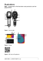
See Figure 2,
Display Description
, in the
Illustrations
section.
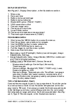
1. Menu area
2. Date and time
3. Battery status percentage
4. Battery status indicator
5. Bluetooth® active (TG267, TG297)
6. USB connection active
7. Camera image area
8. Center spot cross-hairs
9. Laser Pointer active
10. Center spot temperature measurement
11. Thermocouple measurement (TG267)
PROGRAMMING MENU
1. Short press the MENU button to access the menus.
2. Use the up/down arrow buttons to navigate.
3. Use the MENU button to make selections.
4. Use the RETURN button to back up.
5. Pull the trigger to exit the menu system.
6. See menu item list below:
• Main menu: Light (Flashlight), Gallery (saved images), Image
Adjustments, Settings.
• Image Adjustments menu: Image Modes (MSX® or visible cam-
era), Colors (display palettes).
• Settings menu: Measurement, Device, General:
◦ Measurement settings: Center Spot, Emissivity,
Thermocouple.
◦ Device settings: Bluetooth® (TG267, TG297 only), Laser,
Screen brightness, APO.
◦ General settings: Temperature units, Time/Date, Language
selection, System Info (serial number, revision date, etc.),
General System Info (regulatory safety compliance informa-
tion), Factory default reset.
TYPE-K THERMOCOUPLE (TG267)
Connect thermocouple to jack in top compartment. Touch the probe
to a test surface or hold it in air. Read the temperature on the dis-
play (next to
TC
icon). If necessary, enable the thermocouple mode
in the Settings sub-menu (under
Measurements
). Do not exceed
the temperature range printed on the thermocouple label. See Fig-
ure 5,
Type-K Thermocouple
, in the
Illustrations
section.
#NAS100021; r. AD/64725/64725; mul
3
Содержание TG165-X
Страница 1: ...QUICK START Diagnostic Thermal Camera MODELS TG267 TG297 TG165 X...
Страница 72: ...USB C 5V 1A 6 3 70 6 NAS100021 r AD 64725 64725 mul 70...
Страница 73: ......


