background image

T

ABLE OF 

C

ONTENTS


RIGHTS AND LIABILITIES................................................................................................................................ 2


SAFETY INSTRUCTIONS ................................................................................................................................. 2


TABLE OF CONTENTS ..................................................................................................................................... 3


INTRODUCTION AND TECHNICAL DATA ...................................................................................................... 4


MECHANICAL INSTALLATION ........................................................................................................................ 4


ELECTRICAL CONNECTIONS ......................................................................................................................... 4


LOAD CELL CABLE CONNECTION ................................................................................................................ 5


OUTPUT CABLE CONNECTION ...................................................................................................................... 5


CORNER CORRECTION AT SCALES WITH FLINTEC LOAD CELLS........................................................... 6


CLOSING THE JUNCTION BOX....................................................................................................................... 6


SUMMARY OF IMPORTANT SERVICE HINTS ................................................................................................ 7


SERVICE MATERIAL ........................................................................................................................................ 8


Junction Box Type KPF – Technical Manual, Rev. 1.11   July 2008


Page 3 of 8

Содержание KPF-4

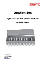
Страница 1: ...Junction Box Type KPF 4 KPF 6 KPF 8 KPF 10 T TE EC CH HN NI IC CA AL L M MA AN NU UA AL L Flintec GmbH Bemannsbruch 9 74909 Meckesheim GERMANY www flintec com...

Страница 2: ...the use of any options or any consumable products other than those designated as Original FLINTEC Products NOTICE The contents of this manual are subject to change without notice Copyright 2007 by Fli...

Страница 3: ...4 MECHANICAL INSTALLATION 4 ELECTRICAL CONNECTIONS 4 LOAD CELL CABLE CONNECTION 5 OUTPUT CABLE CONNECTION 5 CORNER CORRECTION AT SCALES WITH FLINTEC LOAD CELLS 6 CLOSING THE JUNCTION BOX 6 SUMMARY OF...

Страница 4: ...h is more or less dry and protected from environmental stress The junction box itself has to be mounted with the cable glands showing vertically to the bottom A flooding or any tensile load on the cab...

Страница 5: ...ube significantly Unused cable inlets must be closed by the delivered blind plugs If the cable gland nuts are correctly tightened the sealing part of the cable gland must constrict the blind plug sign...

Страница 6: ...kg test load 0 1 kg 500 kg x 1100 0 22 Example 2 400 load cell 10 kg corner error with 5000 kg test load 10 kg 5000 kg x 400 0 8 4 Install the correction resistor into the junction box for the corresp...

Страница 7: ...ing hole must be closed by a blind plug and a gasket 6 The earth screw must be electrically connected with protective earth potential equalisation For doing this only the upper nut should be loosened...

Страница 8: ...ke service kit no 1 but without ring spanner SSG19 Service kit no 3 Article no 5200 U3 for load cells with maximum capacity in the range from 7 5 t to 22 5 t with ring spanner Parts list Description A...

Отзывы: