


Installation, Operation & Maintenance Guide
Style 79
SEAL SUPPORT SYSTEM INSTALLATION
The following steps briefly describe the methods in which a buffer/barrier system should be piped and set up to
support a double cartridge seal. Consult Flex-A-Seal for specific applications and details.
1
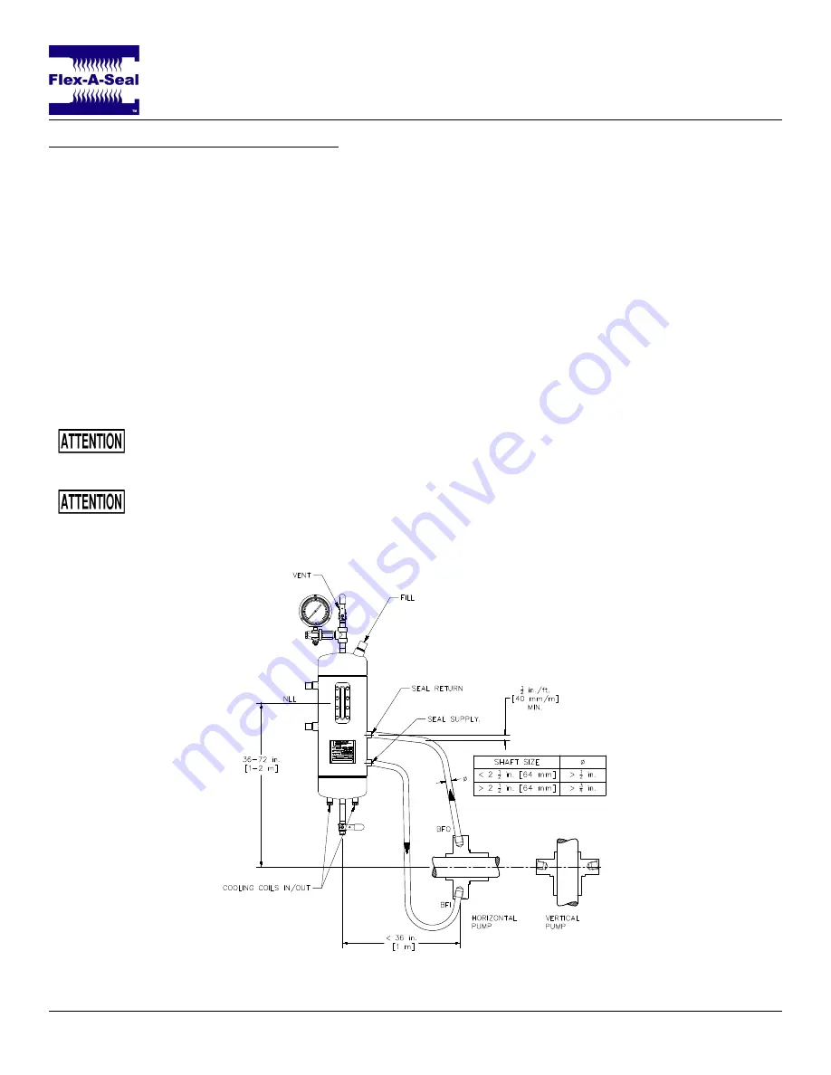
. Correctly make connections between the buffer/barrier fluid system and the mechanical seal according to
the connection labels on the prints. In the case of a Piping Plan 52 or Plan 53A the
SEAL SUPPLY
connection (lower port) on the reservoir must lead to the buffer/barrier fluid in (
BFI
) connection on the seal
gland; the
SEAL RETURN
connection (upper port) on the reservoir must lead to the buffer/barrier fluid out
(
BFO
) connection on the seal gland (
Figure 8
).
• Piping should slope continuously upwards (
1
⁄
2
in./ft. [40 mm/m] minimum) with no relative high points
that would result in trapped air in the tubing.
• For shafts smaller than 2
1
⁄
2
in. [64 mm] use at least
1
⁄
2
in. diameter tubing and at least
3
⁄
4
in. tubing for
larger shafts.
• Use smooth, long radius bends in the piping, minimize 90
◦
elbows, and use 45
◦
bends wherever
possible.
Use thread sealant instead of thread tape. Thread tape has been known to break apart and
enter the buffer/barrier fluid stream, resulting in damage to and premature failure of the
mechanical seal.
Ensure that all tubing/piping is free of pipe strain, which can adversely affect the seal.
2
. Flood the seal support system with the recommended buffer/barrier fluid and ensure all air is properly
vented from the seal.
3
. Check for seal leakage.
Figure 8: Typical installation of a buffer/barrier fluid reservoir.
Page 5 of 7


