background image

 Fläkt  Woods 

8217 GB 2014.07.02 12


Specifications are subject to alteration without notice

TopMaster Air Handling unit 

CONTROL AND REGULATION EQUIPMENT

Alarm

See page 13.

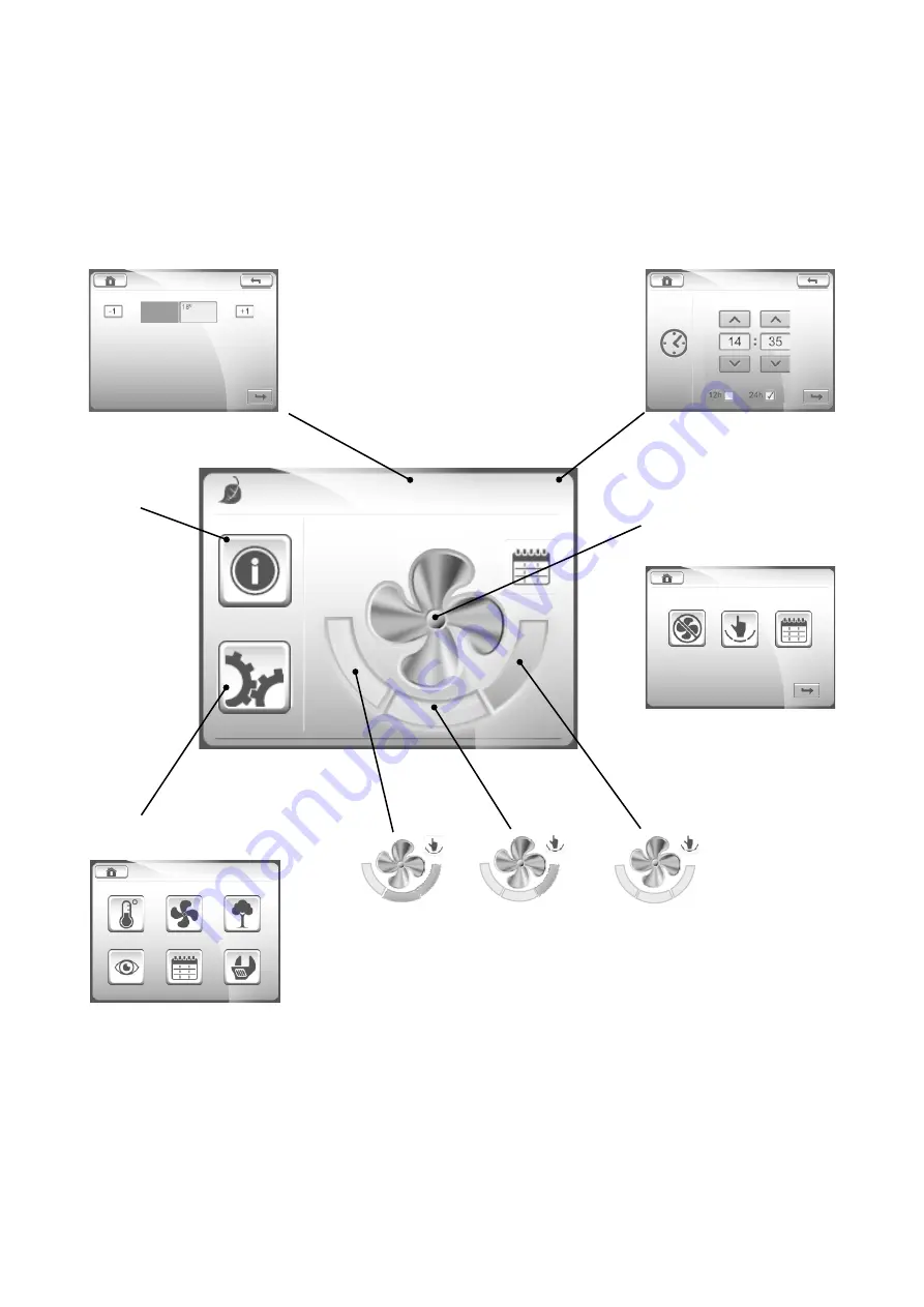
Operation, home screen and submenus

18°C      11:08 

User settings

See page 13.

Setpoint Temp


Setpoint 

Temp

Set Time 

Shortcut to set the 

temperature set point

Shortcut to set the 

time and date

Select operating mode

See page 13.

Trickle or

low speed

Normal or

medium speed

Boost or

high speed

Press each field to select the operating mode.

Only active in Manual mode.

Содержание TopMaster

Страница 1: ...TopMaster Air Handling Unit Control and Regulation Equipment ...

Страница 2: ...rical heater 6 DX cooling 6 Valve actuator and valve for heating and cooling 7 Connection of external components 8 Installation and connection Installation of control panel 9 User instructions General general buttons and symbols 10 Home screen 11 Basic operation overview 12 Submenus 13 Settings Configuring time date and language 14 Login 15 Installers and service personnel 15 Commissioning Wizard ...

Страница 3: ...rminals in the ec trical cabinet A separate switch disconnector must be used e g RDTZ 89 016 Fuse protection The fuse protects the unit s incoming supply Size 030 rated at 10 AT Size 050 rated at 16 AT Fuse protection for DX cooling is carried out separately Feed 3 x 400 V for units with electric coil 1 x 230 V for units with water coil phase connected to terminal L1 1 3 2 4 5 Electrical cabinet 1...

Страница 4: ...on the tie rail the cover is positioned on the electrical cabinet and secured using the appro priate screws see figure 2 The cellular plastic which is semi elastic will slowly adapt to the shape of the cables and in doing so the lead through will seal see figure 3 Information about how the different sensors and accessories should be fitted and connected is provided in the following section Figure ...

Страница 5: ...il Filter monitors accessories The filter monitors GP1 and GP2 are enclosed separately Connect hose to test point Set the required alarm limit across the filter using the knob on the sensor For installa tion see enclosed instruction Air flow monitors accessories The air flow monitors GP1 and GP2 are enclosed sepa rately For installation see enclosed instruction Connect hose to test point Air flow ...

Страница 6: ...nal Connection Comments Circulation CP2 Start C N PE Pump supply pump CP2 230 VAC max 2A CP2 Start N0 L1 Clamp at circulation pump CP2 Alarm NO C Potential free alarm 36 37 input supplied design as NO can be configured Valve actuator SV1 Control Y M G GO 42 43 44 45 Total power consumption for cooling and heating may amount to max 2 A Electric heater If an electric heater has been ordered this is ...

Страница 7: ...le outwards Sensors and accessories Accepted installation method Valve for heating and cooling The valve and valve actuator can be easily installed with out special tools A particle filter should be fitted before the valve to extend its service life 2 way valve VVG The flow is increased by turning the spindle inwards the flow is reduced by moving the spindle outwards Note that the two way valve ca...

Страница 8: ... input 1 8 TMR2 Timer input 2 9 CP1 alarm heating 10 CP2 alarm cooling 11 SV1 CTRL control signal heating 12 SV2 CTRL control signal cooling 13 GT1 14 GT3 15 SK1 Supply supply electric coil 16 TF Supply 17 FF Supply 18 GP3 19 GP4 20 GT5 21 GT2 22 GS1 23 GP7 24 GP1 25 GP2 26 MODB Modbus RS485 27 TF CTRL control signal supply air fan 28 FF CTRL control signal extract air fan Connection of external c...

Страница 9: ...2 Lift the display out of the enclosure 3 Push the connection cable through a suitable hole and if needed make an outlet for the cable in the side of the cover 4 Mount the enclosure directly on the wall or using screws in a junction box Push back the display in the enclosure 5 Connect the cable to the back of the display as shown above Note Please do not touch the electronics Note The control pane...

Страница 10: ...use detergents as these may contain ammonia or other additives IMPORTANT Never spray or pour liquids directly on to the screen Do not clean the screen while the system is on General general buttons and symbols General buttons and symbols The following buttons and symbols are universal and available on many menu pages Home key to return to the Home screen Back button to cancel and return to the pre...

Страница 11: ...erview 18 C 11 08 Operating status Alarm No alarm Alarm B Alarm A Heat recovery active Post heater active Defrosting in progress Cooling active Manual mode Automatic mode Constant pressure Constant air volume Timer 1 Timer 2 Timer 1 Timer 2 Stop Status line Clock Current set point value Trickle or low speed Normal or medium speed Boost or high speed Operating modes ...

Страница 12: ...page 13 Operation home screen and submenus 18 C 11 08 User settings See page 13 Setpoint Temp Setpoint Temp Set Time Shortcut to set the temperature set point Shortcut to set the time and date Select operating mode See page 13 Trickle or low speed Normal or medium speed Boost or high speed Press each field to select the operating mode Only active in Manual mode ...

Страница 13: ...re you set the desired setpoint The default factory setting is 18 C Other temperatures are read only Fan control status Fan speeds and possible pressures and flow rates only for reading Air quality Not in use for TopMaster System overview Summarizes the unit s main operating para meters See section Parameter list on pages 23 27 Schedules See section Schedules on pages 17 19 Advanced operations See...

Страница 14: ...nguage Login Settings Set Language 2 Press the spanner button 3 In this menu you set the date time and language It is also possible for installers and service personnel to log in and access additional parameters Time Date Set Time 1 Set the time and press the Confirm button Set Date 2 Set the date and press the Confirm button 1 Choose the appropriate language flag and press the Confirm button Note...

Страница 15: ...00 This can be changed later Enter passcode 1 Enter the correct passcode and press the Confirm button For commissioning of fans see following section Commissioning Wizard on page 16 For other settings see Parameter list on pages 23 27 Settings for installer and service personnel 1 Schedule 2 Run Commissioning Wizard 4 Fan Control 5 Heating Cooling 3 Timer Control Settings 6 Air Qualty 7 Alarm Conf...

Страница 16: ...alue Option 1 Use the buttons Option 2 Use the numerical keypad confirm with Commissioning Wizard The Commissioning Wizard allows the fan settings to be configured in a simple and intuitive manner The Commissioning Wizard is accessed by selecting the Run Commissioning Wizard option from the Set tings screen 1 Schedule 2 Run Commissioning Wizard 4 Fan Control 5 Heating Cooling 3 Timer Control Setti...

Страница 17: ... program the weekly schedule with the required times Then use any single date programs and the period to enter exceptions such as weekends and holidays Each schedule also needs to be activated This is done by pressing the grey tick button A green tick indicates that the schedule is active Priority When several enabled applications overlap the following applies Highest priority Date period 4 Date p...

Страница 18: ...Stop Tem Setpoint Rel 0 C From To Fri Fri Daily 17 00 18 00 Schedules cont Example 3 Below is an example of a weekly schedule configured to run the fans at normal speed from 08 00 to 18 00 Monday to Friday At all other times the fans are configured to run at trickle speed At trickle speed the temperature set point will be decreased by two degrees Day Time Fan speed Temp setpoint Monday 8 18 Normal...

Страница 19: ...ec 2014 Stop date 26 Dec 2014 Rel Single date schedule 1 4 A single date schedule is defined as a one off schedule that automati cally starts and finishes on the same date Example The unit must be switched off on 6 June Date period schedule 1 4 A date period schedule is defined as a one off schedule that is configured to run between any two dates Example The unit must be switched off between 24 De...

Страница 20: ...tant supply air temperature the con troller works from a fixed setpoint and the supply air temperature Based on these parameters the controller controls the current heating heat recovery and cooling sequences Extract air control The exhaust air temperature gives a good average value of the temperature in different rooms Using this the unit controls the supply air temperature to maintain the extrac...

Страница 21: ... Cascade reference 1 Selects outdoor temperature compensation 3 Cascade A 0 05 When the sensor gets colder than given setpoint value 4 Cascade B 0 03 When the sensor gets hotter than given setpoint value 5 Min temp 15 C Sets lowest supply air temperature 6 Max temp 25 C Sets highest supply air temperature Control functions cont Setpoint Outdoor temperature compensation Outdoor temperature C 30 25 ...

Страница 22: ... time off kl 22 15 Stop time for night cooling test Max time 540 minutes Maximal activation time for night cooling 6 Pressure or flow control Pressure control COP Control principle in which the unit maintains a constant duct pressure Normally used in variable flow systems VAV Pressure sensor is supplied as a loose accessory Size 030 050 k value extract air fan 56 41 k value supply air fan 55 49 4 ...

Страница 23: ...ut Pre heater R No such function in TopMaster Output Heat recovery R 0 100 Outout Cooling R 0 100 Summer Winter mode R Summer Winter Supply air temperature R 40 100 C Supply air temperature R 40 100 C Extract air temperature R 40 100 C Cold corner temperature R No such function in Topmaster Freeze protection temperature R 40 100 C Only in case of water heating Setpoint set R W 15 35 C 18 Operation...

Страница 24: ...rameter is active Supply air pressure setpoint R W 0 2000 Pa 150 Extract air pressure setpoint R W 0 2000 Pa 150 If flow control Flow control supply air R W Yes No Yes Flow control extract air R W Yes No Yes Only SF EF slave R W Yes No No Proportion SF EF R W 0 200 100 Only if the above parameter is active Supply air flow low speed R W 0 9999 l s 80 Supply air flow normal speed R W 0 9999 l s 100 ...

Страница 25: ...ummer R W Summer Winter Winter 5 7 Freeze protection See also page 20 22 Keeping warm R W 0 50 C 25 Setpoint min mode temp R W 0 50 C 12 Setpoint freeze protection alarm R W 0 50 C 5 Pump stop R W Yes No Yes No continuous operation of pumps Heat pump runs when heating is required cooling pump runs when Pump stop mode R W Summer Winter heating cooling S W heat pump runs in winter heating cooling co...

Страница 26: ... R W 0 9999 s 5 Sensor fault Cold corner delay Not used in TopMaster Sensor fault UI1 delay Not used in TopMaster Sensor fault UI2 delay Not used in TopMaster Sensor fault UI3 delay Not used in TopMaster Sensor fault UI4 delay Not used in TopMaster Sensor fault UI5 delay Not used in TopMaster Fan monitor supply air delay R W 0 9999 s 2 Fan monitor extract air delay R W 0 9999 s 2 Rotor pressure sw...

Страница 27: ...0 Time before the screen saver is activated in the control panel 8 4 Modbus Sea also the Modbus manual Address BMS R W 2 Baud rate R W 9600 19200 9600 38400 Parity R W none odd even none Data bit R W 7 8 8 Stop bit R W 1 2 1 8 5 MAC address MAC address L Displays the network card MAC address 8 7 Password Automatic logout R W Yes No Yes Password 1 R W 0000 9999 0000 The password can be changed If p...

Страница 28: ...wide range of air climate and air movement solutions Our collective experience is unrivalled We are constantly aiming to provide systems that precisely deliver the required features and performance as well as maximum energy efficiency Fläkt Woods Group SA 18 avenue Louis Casaï CH 1209 Geneva Switzerland Tel 41 22 309 3800 email info flaktwoods com www flaktwoods com See global website for internat...

Отзывы: