


Instruction Manual
D104296X012
LCP200 Local Control Panel
August 2018
17
Emergency Demand and Reset through Local Control Panel
1. Press the Middle (Trip) pushbutton.
2. Observe that the valve moves to it Trip position.
3. Observe that the Middle (Red/Trip) light comes on solid and the Bottom (Yellow/Ready-to-Reset) light is on solid.
4. If the relay contacts are being used, verify that the Trip contact changes state for 1.5 to 3 seconds when the middle
pushbutton is pressed.
5. Press the Top (Reset) pushbutton.
6. Observe that the middle light goes off, the valve moves to its normal operating position, and then the Top
(Green/Normal) light comes on solid.
7. If the relay contacts are being used, verify that the Reset contact changes state for 1.5 to 3 seconds when the top
pushbutton is pressed.
Maintenance
The LCP200 has six major components; the housing, lights, buttons, conduit connections, electronics, and contacts. If
a light is not working it can be replaced as a module. If any of the buttons are not working then the front panel needs
to be replaced. The conduit connections do not normally need replacement. The electronics module, which includes
the relay contacts, can be replaced as an assembly.
The LCP200 enters a bench mode when it is powered and not connected to a digital valve controller, i.e. the auxiliary
terminals are not connected to the DVC6200 SIS. In this mode, the light next to each button will be on solid when the
button is pressed. The corresponding relay contact will change state as long as the respective button is pressed. This
can be used to identify stuck buttons, faulty lights, or relay contacts.
Note
Parts kits for the following maintenance procedures are available on page 20 and 20.
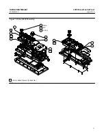
Refer to figure 10 and 11 for key number locations.
Replacing the LED Assembly
The LED's can be replaced in the field without removing power.
CAUTION
Ensure the LED enclosure does not get contaminated with dust, moisture, or other contaminants during this procedure.
Exposure to dust, moisture, or other contaminants can damage the electronics.
1. Unscrew the four socket cap screws (key 45) holding the LED module (key 32) in place using a 2.5 mm hex key and
remove the LED module and the LED base O-ring (key 46). Also remove the four O-rings (key 47).
2. Replace with new O-rings and LED module. Apply silicone lubricant to the O-rings.
3. Replace the required lens cap on the LED module. Install the 4 socket cap screws and tighten to a torque of
0.77 N•m (6.8 lbf•in) +/- 10% .