


Instruction Manual
D200319X012
377 Trip Valve
August 2012
9
GE08412‐A
A6905‐1
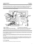
Figure 7. Fisher 377D Trip Valve Shown in Tripped Condition
SPRING
VALVE PLUG
UPPER
DIAPHRAGM
EXHAUST
PORT
SUPPLY
PRESSURE
LOWER
DIAPHRAGM
PORT D
PORT E
LOWER
PORTS
PORT F
PORT C
PLUG
ASSEMBLIES
UPPER PORTS
PORT B
PORT A
VENT
MAIN SPRING
ACTUATOR
CONTROL
DEVICE
CHECK
VALVE
VOLUME
TANK
SUPPLY PRESSURE
CONTROL PRESSURE TO TOP OF CYLINDER (BLOCKED)
CONTROL PRESSURE TO TOP BOTTOM OF CYLINDER (BLOCKED)
PRESSURE TO TOP OF CYLINDER (FROM VOLUME TANK)
PRESSURE FROM BOTTOM OF CYLINDER (VENTING)
LOWER DIAPHRAGM LOADING PRESSURE (BEING VENTED)
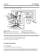
3. Connect an adequately sized gauge for the supply pressure reading to the supply line. To make the fail action more
visible, adjust the control device signal so that actuator stem movement is visible when the trip valve is actuated.
4. For the lock‐in‐last‐position mode, remove the plugs from ports C and F.
5. Set the supply pressure at the required trip point pressure (refer to table 1 for the trip point limits).
Note
For proper calibration, completely back out the set screw (key 2) until there is no spring compression. Then, set the trip point by
turning the set screw clockwise to compress the spring.
6. Slowly turn the set screw clockwise to compress the spring until the trip valve trips. When the trip valve trips in the
fail‐up or fail‐down mode, the actuator stem moves to the appropriate position. In the lock‐in‐last‐position mode,
the actuator stem does not move, however, air will be heard escaping from ports C and F. This is because pressure is
being released from both sides of the actuator cylinder.


