Fisher 377 Скачать руководство пользователя страница 16

Instruction Manual

D200319X012

377 Trip Valve

August 2012

16

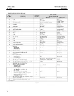
Table 2. Common Parts (continued)

KEY

NUMBER

DESCRIPTION

QUANTITY
REQUIRED

PART MATERIAL

Trip Valve Construction

Aluminum

Stainless Steel

15

O‐ring

Nitrile

(1)

Fluorocarbon

Nitrile

(1)

Fluorocarbon

16

Pilot body assembly

Aluminum/anodized aluminum

CF3M SST casting
(316L SST, cast)

17

Diaphragm

Nitrile

(1)

Fluorocarbon

Nitrile

(1)

Fluorocarbon

18

Pusher plate

Aluminum

S31603 (316L SST)

19

Diaphragm spacer

Aluminum

CF3M SST casting

20

Cap screw (not shown)

4

Pl steel

S31600 (316 SST)

21

Body

Aluminum

CF3M SST casting

22

Stem

(1)

2

Stainless steel

S31603

23

O‐ring

2

Nitrile

(1)

Fluorocarbon

Nitrile

(1)

Fluorocarbon

24

Plug assembly

2

Brass/chloroprene

(1)

Brass/fluorocarbon

S31603/chloroprene
S31603/fluorocarbon

25

Spring

2

Pl steel

S30200 (302 SST)

26

O‐ring

2

Nitrile

(1)

Fluorocarbon

Nitrile

(1)

Fluorocarbon

27

O‐ring retainer screw

2

Stainless steel

S30300 (303 SST)

29

O‐ring (top‐mounted only)

2

Nitrile

(1)

Fluorocarbon

Nitrile

(1)

Fluorocarbon

30

Cap screw

top mounted
yoke mounted
bracket mounted

2
1
1

Pl steel

Stainless steel

31

Manifold assembly

Aluminum

Aluminum

32

Cap screw (use w/manifold assembly) 
(not shown)

2

Pl steel

Stainless steel

33

Cap screw (not shown)

yoke mounted
bracket mounted

Steel

Stainless steel

34

Pipe plug (for 377L only) (not shown)

2

Brass, use with all actuators except 1069
S31600, use with 1069 actuator

S31600

35

Pipe plug (boss or bracket  mounted w/o manifold
assembly for 480‐16 only) (not shown)

Pl steel

Stainless steel

36

Check valve, (for 377D, 377U 377CW
and 377CCW only) (not shown)

For use w/o 2625
For use with 2625

Brass or S31600

S31600

37

Vent assembly (not shown)

Plastic

Plastic

Top mounted 377D, 377U 377CW
and 377CCW

1

Top or boss mounted 377D, 377U
377CW and 377CCW with flow control valve

1

Boss mounted 377D, 377L, 377U, 
377CW and 377CCW

2

37

Flow control valve (optional on 377D, 377U 377CW
and 377CCW trip valves)

Stainless steel

Stainless steel

39

Lithium grease (not furnished with trip valve)

1. Included in Repair Kit

-continued-

Содержание 377

Страница 1: ...fully trained and qualified in valve actuator and accessory installation operation and maintenance To avoid personal injury or property damage it is important to carefully read understand and follow all of the contents of this manual including all safety cautions and warnings If you have any questions regarding these instructions contact your Emerson Process Management sales office before proceedi...

Страница 2: ...4 NPT internal Temperature Capabilities 1 Nitrile Diaphragms and O Rings 40 to 82_C 40 to 180_F Fluorocarbon Diaphragms and O Rings 18 to 104_C 0 to 220_F Volume Tank Maximum Internal Working Pressure for 377D 377U 377CW and 377CCW trip valves Standard 10 3 bar 150 psig for non ASME approved applications See note on page 7 ASME Approved Applications Rated 10 3 bar 150 psig maximum 9 3 bar 135 psig...

Страница 3: ...VALVE PLUG SPRING SUPPLY CONNECTION LOWER DIAPHRAGM W4303 1 IL Specifications Specifications for 377 trip valves are given in table 1 Educational Services For information on available courses for 377 trip valves as well as a variety of other products contact Emerson Process Management Educational Services Registration P O Box 190 301 S 1st Ave Marshalltown IA 50158 2823 Phone 800 338 8158 or Phone...

Страница 4: ...f the system component D Check with your process or safety engineer for any additional measures that must be taken to protect against process media D If installing into an existing application also refer to the WARNING at the beginning of the Maintenance section in this instruction manual The 377 trip valve is normally ordered as part of a control valve assembly Follow the procedure in the appropr...

Страница 5: ...APACITY FOR 2625 BOOSTERS ALSO IF THE 2625 BOOSTER IS TO BE NIPPLE MOUNTED THE BOOSTER MUST BE MOUNTED TO A 1 2 NPT OR LARGER CYLINDER CONNECTION SOME SMALLER CYLINDERS CANNOT BE TAPPED THIS LARGE CONTACT YOUR EMERSON PROCESS MANAGEMENT SALES OFFICE FOR AVAILABILITY ON SPECIFIC TYPES AND SIZES 3 4 NPT OR 1 2 NPT PIPING 21B3154 C 1 2 O D COIL VOLUME TANK TUBING VOLUME TANK VENT Supply Pressure Requ...

Страница 6: ... SPECIFIED MUST HAVE ADEQUATE CAPACITY FOR 2625 BOOSTERS ALSO IF THE 2625 BOOSTER IS TO BE NIPPLE MOUNTED THE BOOSTER MUST BE MOUNTED TO A 1 2 NPT OR LARGER CYLINDER CONNECTION SOME SMALLER CYLINDERS CANNOT BE TAPPED THIS LARGE CONTACT YOUR EMERSON PROCESS MANAGEMENT SALES OFFICE FOR AVAILABILITY ON SPECIFIC TYPES AND SIZES 3 4 NPT OR 1 2 NPT PIPING 21B3153 B Note During normal operation an adequa...

Страница 7: ...ressure To ensure safety valve seat tightness and longevity the recommended maximum supply pressure is 9 3 bar 135 psig Standard volume tanks supplied in Europe must conform to Directive 2009 105 EC for simple pressure vessels The maximum pressure rating is stated on the tank For standard applications not ASME approved a DOT tank is used This tank is rated at 14 5 bar 240 psig in LP service When u...

Страница 8: ...D must receive the operating pressure that is intended for the bottom of the actuator cylinder Depending on the actuator type and accessories being used this operating pressure will be from a valve positioner or switching solenoid e Trip valve port E must provide operating pressure to the bottom of the actuator cylinder Always connect this port to the bottom of the actuator cylinder f Trip valve p...

Страница 9: ...the fail action more visible adjust the control device signal so that actuator stem movement is visible when the trip valve is actuated 4 For the lock in last position mode remove the plugs from ports C and F 5 Set the supply pressure at the required trip point pressure refer to table 1 for the trip point limits Note For proper calibration completely back out the set screw key 2 until there is no ...

Страница 10: ...ER STATIC LOWER DIAPHRAGM LOADING PRESSURE BEING VENTED GE08414 A A6906 1 7 Tighten the hex nut key 3 and install the adjusting screw cap key 1 8 For the lock in last position mode reinstall the plugs in ports C and F 9 Reset the control device for normal operation Principle of Operation 377D Trip Valve Figure 7 illustrates trip valve operation in the fail down mode In normal operation supply pres...

Страница 11: ... TANK LOWER DIAPHRAGM LOADING PRESSURE BEING VENTED GE08413 A A2284 6 When the supply pressure falls below the trip point the exhaust port opens venting the supply pressure that is loading the lower diaphragm This causes the upper ports of the plug assemblies to close and disconnect normal pressure from the control device to the actuator Volume tank pressure is then applied through ports C and B t...

Страница 12: ... upon the severity of service conditions Be sure to note the location of all pressure connections to ensure proper trip valve installation upon reassembly or use the installation procedures in this instruction manual All key numbers refer to figure 10 unless otherwise indicated WARNING Avoid personal injury or property damage from sudden release of process pressure or bursting of parts Before perf...

Страница 13: ...taken during the following procedure to prevent damage to the upper diaphragm 1 Remove the adjusting screw cap key 1 and loosen the hex nut key 3 that locks the set screw key 2 Loosen the set screw to remove all spring compression 2 Remove the cap screws key 7 not shown from the spring case and lift off the body assembly key 16 and attached parts from the trip valve body key 21 Note the orientatio...

Страница 14: ...to the installation and calibration procedures Replacing Stem Plug Assembly Parts 1 Remove the cap screws key 76 not shown from the body key 21 and remove the manifold key 73 and the stem plug assemblies keys 22 23 24 26 and 27 2 Inspect the upper and lower O rings keys 23 and 26 for nicks or wear If the lower O ring needs to be replaced remove the O ring retainer screw key 27 before installing th...

Страница 15: ...it include valve plugs stems plug assemblies and nitrile diaphragms O rings and gasket keys 12 14 15 17 22 23 24 26 29 63 74 and 89 Aluminum Construction R377X000012 Stainless Construction R377X000032 Parts List Table 2 Common Parts KEY NUMBER DESCRIPTION QUANTITY REQUIRED MATERIAL Trip Valve Construction Aluminum Stainless Steel 1 Adjusting screw cap Plastic Plastic 2 Set screw Pl steel S31600 31...

Страница 16: ...00 303 SST 29 O ring top mounted only 2 Nitrile 1 Fluorocarbon Nitrile 1 Fluorocarbon 30 Cap screw top mounted yoke mounted bracket mounted 2 1 1 Pl steel Stainless steel 31 Manifold assembly Aluminum Aluminum 32 Cap screw use w manifold assembly not shown 2 Pl steel Stainless steel 33 Cap screw not shown yoke mounted bracket mounted Steel Stainless steel 34 Pipe plug for 377L only not shown 2 Bra...

Страница 17: ... w 2625 or ASME approved volume tanks 1 req d per volume tank Pl steel S31600 46 Pipe tee For two standard volume tanks w o 2625 For two standard volume tanks w 2625 or two ASME approved volume tanks For one ASME approved volume tank w o 2625 For one ASME approved volume tank w 2625 Galvanized iron S31600 47 Pipe nipple For two standard volume tanks w o 2625 For two standard volume tanks w 2625 or...

Страница 18: ...mounted 2 Pl steel Stainless steel 89 Gasket Standard High temperature Nitrile nylon 1 Polyacrylate nylon Nitrile nylon 1 Polyacrylate nylon 95 Mounting plate not shown Bracket mounted Pl steel Stainless steel 1 Included in Repair Kit 2 Not required for stainless steel trip valve Fittings Note The following is a list of tubing fittings and pipe fittings used for trip valve installation Key numbers...

Страница 19: ...st 2012 19 Figure 10 Trip Valve Assembly APPLY LUB 49A3195 C IL NOTE KEY NUMBERS 7 20 64 65 76 78 79 80 88 NOT SHOWN ALUMINUM CONSTRUCTION STAINLESS STEEL CONSTRUCTION APPLY LUB GE51600 A NOTE KEY NUMBERS 7 20 30 33 36 37 64 65 76 78 79 80 88 NOT SHOWN ...

Страница 20: ...h are available upon request We reserve the right to modify or improve the designs or specifications of such products at any time without notice E 1984 2012 Fisher Controls International LLC All rights reserved Fisher and FIELDVUE are marks owned by one of the companies in the Emerson Process Management business unit of Emerson Electric Co Emerson Process Management Emerson and the Emerson logo ar...

Отзывы: