Instruction Manual
D200319X012
377 Trip Valve
August 2012
2
Table 1. Specifications
Available Configurations
377 Trip Valve:
Includes check valve, but no volume
tank: user configured for locking position. For field
use or replacement.
When supply pressure falls below the trip point,
377D Trip Valve:
Fails actuator piston down. Includes
check valve and volume tank.
377L Trip Valve:
Locks actuator piston in the last
position.
377U Trip Valve:
Fails actuator piston up. Includes
check valve and volume tank.
377CW Trip Valve:
Fails fully clockwise to close valve.
Requires check valve and volume tank. Trip valve
moves piston to either up/down position and requires
actuator configuration for actual clockwise
movement.
377CCW Trip Valve:
Fails fully counterclockwise to
close valve. Requires check valve and volume tank.
Trip valve moves piston to either up/down position
and requires actuator configuration for actual
counterclockwise movement.
All 377 Trip Valves can be converted to any of the
above fail modes with minor hookup changes
Allowable Supply Pressure for Trip Valve
(1)
Maximum:
10.3 bar (150 psig)
Minimum:
3.8 bar (55 psig)
Outlet Pressure
Normal Operation:
Pressure from control device
Fail‐Up or Fail‐Down Mode:
Maximum volume tank
pressure
Lock‐In‐Last‐Position:
Respective cylinder pressure
Trip Point
(2)
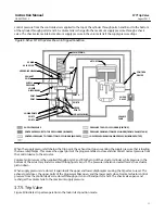
Adjustable from a minimum of 2.8 bar (40 psig) to a
maximum of 72 percent of supply pressure;
see figure 4
Reset:
12.5 to 33 percent above adjusted trip point
Flow Coefficients (C
v
)
(3)
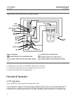
Depends on flow path (shown in figure 3) as follows:
Port A to Port B and Port D to Port E: 0.5
Port B to Port C and Port E to Port F: 0.6
Pressure Connections
1/4 NPT internal
Temperature Capabilities
(1)
Nitrile Diaphragms and O‐Rings:
-40 to 82
_
C
(-40 to 180
_
F)
Fluorocarbon Diaphragms and O‐Rings:
-18 to 104
_
C
(0 to 220
_
F)
Volume Tank Maximum Internal Working Pressure
(for 377D, 377U, 377CW and 377CCW trip valves)
Standard:
10.3 bar (150 psig) for non‐ASME approved
applications. See note on page 7.
ASME Approved Applications:
Rated 10.3 bar (150
psig), maximum; 9.3 bar (135 psig), recommended.
See note on page 7.
Hazardous Area Classification
Complies with the requirements of ATEX Group II
Category 2 Gas and Dust
Mounting
Top‐Mounted:
Manifold‐mounted between a Fisher
3570 positioner and 480 actuator (manifolds cannot
be supplied with Fisher 585C, 1061, 1066, and 1069
piston actuators)
Side‐Mounted:
Yoke‐mounted or bracket‐mounted
for use with a FIELDVUE™ DVC6200, DVC6200f,
DVC6000 or DVC6000f digital valve controller
Approximate Weight
Trip Valve
A
luminum:
0.95 kg (2.1 pounds)
Stainless Steel
: 2.31 kg (5.1 pounds)
Mounting Manifold:
0.5 kg (1.2 pounds)
Volume Tank:
Varies between 5.4 and 363 kg (12 and
800 pounds) depending on size
Declaration of SEP
Fisher Controls International LLC declares this
product to be in compliance with Article 3 paragraph
3 of the Pressure Equipment Directive (PED) 97 / 23 /
EC. It was designed and manufactured in accordance
with Sound Engineering Practice (SEP) and cannot
bear the CE marking related to PED compliance.
However, the product
may
bear the CE marking to
indicate compliance with
other
applicable European
Community Directives.
1. The pressure/temperature limits in this document and any applicable standard or code limitation should not be exceeded.
2. If the trip point is not specified, the trip point is factory set at 72 percent of supply pressure or 2.8 bar (40 psig), whichever is higher.
3. Values represent nominal C
v
measures for each port pair using a trip valve/actuator combination.


