


Instruction Manual
D200319X012
377 Trip Valve
August 2012
13
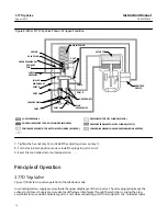
1. Isolate the actuator/valve assembly from the process loop.
2. Provide a means of monitoring the supply pressure input to the trip valve.
3. Starting with normal supply pressure applied to the trip valve, slowly reduce the supply pressure until the trip valve
trips. The trip valve should trip at the pressure set during the calibration procedures.
4. Increase the supply pressure until the trip valve resets. This should occur at a supply pressure 12.5 to 33 percent
above the trip point.
5. If the trip valve fails to trip and reset at the calibrated settings, refer to the calibration procedures.
6. If the trip valve will not calibrate, continue with the following maintenance procedures.
Trip Valve Part Replacement Procedures
WARNING
Refer to the WARNING at the beginning of the Maintenance Section in this instruction manual.
Isolate the control valve from the line pressure, release pressure from both sides of the valve body, and drain the
process media from both sides of the valve. If using a power actuator, also shut off all pressure lines to the power
actuator, release all pressure from the actuator. Use lock‐out procedures to be sure that the above measures stay in
effect while you work on the equipment.
Replacing Diaphragms and Valve Plug Parts
CAUTION
Care must be taken during the following procedure to prevent damage to the upper diaphragm.
1. Remove the adjusting screw cap (key 1), and loosen the hex nut (key 3) that locks the set screw (key 2). Loosen the
set screw to remove all spring compression.
2. Remove the cap screws (key 7, not shown) from the spring case, and lift off the body assembly (key 16) and
attached parts from the trip valve body (key 21). Note the orientation of the vent and supply connections to the
body (see figure 1).
3. Remove the cap screws (key 20, not shown) and separate the diaphragm (key 17), diaphragm spacer (key 19), and
the pusher plate (key 18) from the rest of the body assembly. Lift off the spring case (key 4), travel stop (key 75,
aluminum housing only), upper spring seat (key 5), and spring (key 6).
4. Take out the upper diaphragm assembly (keys 8, 9, 10, 11, 12, 13, 14, and 15).
5. Carefully unscrew the spring seat (key 9) from the upper diaphragm retainer (key 13). Be careful not to lose the
valve plug (key 14), valve guide (key 8), and spring (key 10). Also be careful not to damage the upper diaphragm
(key 12).
6. Inspect the upper diaphragm, valve plug, body assembly, and O‐ring (key 15) for nicks, scratches, or cuts that could
cause leakage. Replace parts as necessary. Make sure the O‐ring (key 15) is properly lubricated (key 77) to avoid
leakage past the O‐ring.
7. With the spring (key 10), spring seat (key 9), valve plug (key 13), valve guide (key 8), diaphragm washer (key 11),
and upper diaphragm (key 12) in place, screw the upper diaphragm retainer (key 13) and spring seat (key 9)
together, being careful not to damage the diaphragm.


