


Instruction Manual
D200319X012
377 Trip Valve
August 2012
14
8. Inspect the lower diaphragm (key 17) and pusher plate (key 18), and replace them if damaged or excessively worn.
9. Place the upper diaphragm assembly (keys 8, 9, 10, 11, 12, 13, 14, and 15), travel stop (key 75, aluminum housing
only), spring (key 6), upper spring seat (key 5), diaphragm spacer (key 19), pusher plate (key 18), and diaphragm
(key 17) onto the body assembly (key 16). Secure the body assembly parts to the spring case (key 4) with the cap
screws (key 20). Position the supply and vent connections as noted in step 2.
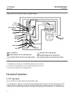
10. Note the orientation of the supply connection to the body (see figure 1). Attach the assembly, from step 9, to the
body (key 21) with the cap screws (key 7, not shown). Tighten the screws.
11. Refer to the installation and calibration procedures.
Replacing Stem/Plug Assembly Parts
1. Remove the cap screws (key 76, not shown) from the body (key 21), and remove the manifold (key 73) and the
stem/plug assemblies (keys 22, 23, 24, 26, and 27).
2. Inspect the upper and lower O‐rings (keys 23 and 26) for nicks or wear. If the lower O‐ring needs to be replaced,
remove the O‐ring retainer screw (key 27) before installing the new O‐ring. The upper O‐ring simply slips over the
end of the stem (key 22). Lightly lubricate O-rings (key 77) prior to reassembly.
3. Inspect the stem/plug assemblies, inspect the valve seats in the body (key 21), and replace any parts if necessary.
4. When stem/plug assembly maintenance procedures are complete, carefully slide the stem/plug assemblies
(keys 22, 23, 24, 26, and 27) and springs (key 25) into the body. Attach the manifold (key 73) to the bottom of the
body (key 21), and tighten the screws (key 76).
5. Refer to the installation and calibration procedures.


