15465 Rev F 5/2/97 P/N 15465:F
8
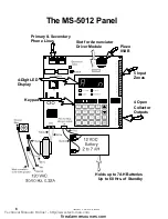
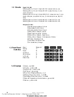
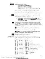
1.4 Displays
1.3 Front Panel
Switches
Input Circuits
Initiating Device Circuit 1 (Style B) N.O. contact devices only.
Initiating Device Circuit 2 (Style B) N.O. contact devices, 2-wire
smoke detectors.
Initiating Device Circuit 3 (Style B/D) N.O. contact devices, 2-wire
smoke detectors, waterflow devices. (2-wire detectors use Style B
only)
Initiating Device Circuit 4 (Style B) N.O. contact devices only.
Initiating Device Circuit 5 (Style B) N.O. contact devices only.
Output Circuits
❏
Notification Appliance Circuit
❏
Resettable Power Circuit
❏
Non-Resettable Power Circuit
❏
Relay Driver Output - Alarm
❏
Relay Driver Output - Trouble
❏
Relay Driver Output - Supervisory
❏
Relay Driver Output - Communicator Failure
❏
Primary Telephone Line
❏
Secondary Telephone Line
❏
12 Volt Battery Charger
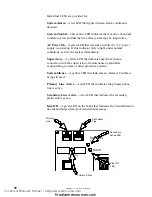
Reset
Digits 0-9
Silence
A
Mode
B
Up Arrow
C
Down Arrow
D
1st Event
E
Enter Store
F
❏
Alarm - red LED
❏
Trouble - yellow LED
❏
Supervisory - yellow LED
❏
AC Power - green LED
❏
Four, Seven Segment Displays - red
❏
Primary Phone Line Active - red LED
❏
Secondary Phone Line Active - red LED
❏
"Kissoff" Signal from Central Station - green LED
❏
Silence - yellow LED
1.2 Circuits
u
v
w
123f
q'
456e
r
789d
s
a0bc
t
Technical Manuals Online! - http://www.tech-man.com
firealarmresources.com


