


Ä
7.4
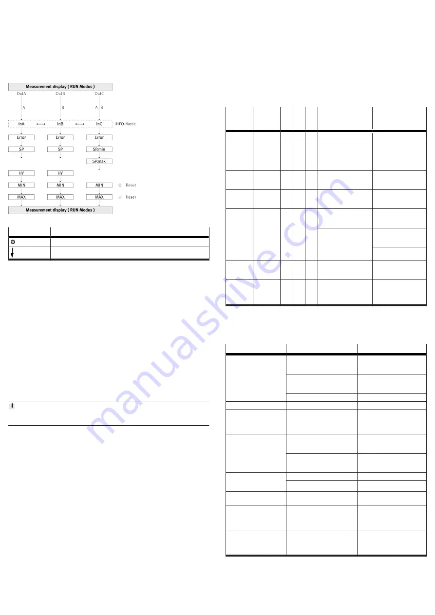
Displaying parameters (INFO/SHOW mode)
Requirement: the sensor is ready for operation (RUN mode).
1. Press A button, B button or A and B button.
Ä
Display shows the relevant input value or an error number.
2. To display each of the following parameters, press the A button, B button or A
and B button .
3. At the end of the SHOW mode, the relevant minimum and maximum values
are displayed. To reset the display of the minimum and maximum values,
press the Edit button.
Ä
RUN mode is active.
Fig. 14: Measured value indicator for SHOW mode
Key
Meaning
Edit button
A button, B button or A and B button
Tab. 17: Legend for measured value indicator (RUN mode)
8
Operation and use
8.1
Notes on operation
Type SOPA-C..
•
To prevent contamination of the sensor modules and the measuring nozzles,
switch on the measuring air.
•
Activate the exhaust air to clean contaminated measuring nozzles.
The switching status of the valves, which are integrated in the control module and
used for activating the measuring and exhaust air, is indicated by the status LED
[Sense] and [Clean].
Type SOPA-C..-H
•
The electric manual override function for the measuring and exhaust air on
the control module can be deactivated by switching off the supply voltage for
the manual override.
Ä
The LED which indicates the ready status of the manual override is then
switched off.
8.2
Restoring Factory Settings (Restore)
By resetting to the factory settings, the current settings are lost. Note down
current settings before resetting.
1. Switch off operating voltage.
2. Press and hold the A pushbutton, B pushbutton and Edit button.
3. Switch on the operating voltage.
–
[CLER] is displayed.
–
The factory settings are restored . RUN mode is active.
8.3
Using the differential pressure regulator
In order to enable faster response times with low measuring distances or com-
pletely sealed measuring nozzles, a differential pressure regulator (LRLL-1/8-
QS-6) can be used instead of the vent screw. The valve function enables the
pressure to be exhausted significantly quicker than via the vent screw.
Connecting and checking the differential pressure regulator
1. Remove the vent screw (SW 14).
2. Mount the differential pressure regulator (LRLL-1/8-QS-6) n the connection
for the vent screw (
3. Press the CLEAN pushbutton (CLEAN = OFF) and then the SENSE pushbutton
(SENSE = ON) on the control module.
4. Make sure that there is not an object in the area of the measuring nozzles .
5. Turn the adjusting screw on the differential pressure regulator clockwise
(towards LOW) until air stops flowing from the differential pressure regulator.
6. Turn the adjusting screw on the differential pressure regulator anticlockwise
(towards HIGH) until air starts to flow from the differential pressure regulator.
Checking the settings of the differential pressure regulator
1. Seal the measuring nozzle (e.g. workpiece inserted).
2. Press the CLEAN key (CLEAN = OFF) on the control module.
Ä
Sensor module is supplied with operating pressure. [SUP.P] is displayed.
3. Press and hold the SENSE pushbutton (SENSE = ON) on the control module
until [SUP.P] is no longer displayed.
4. If the delay ([SUP.P] in the display) is too great, reduce the time by turning the
control valve (towards HIGH).
9
Maintenance and Care
1. Switch off the energy sources (operating voltage, compressed air).
2. Clean sensor with non-abrasive cleaning agents.
10
Malfunctions
10.1
Error messages
Indica-
tion on
display
Event
code
[hex]
G
1)
E
2)
S
3)
Error
Remedy
[Er01]
0x5000
4
3
4
Sensor module defective
Replace sensor module
[Er14]
0x180E
2
2
1
Supply pressure (InC)
outside the measuring
range (
>
2 bar,
>
0.2 MPa); signal cannot
be evaluated
Observe the measuring
range
[Er17]
0x5111
4
3
3
Undervoltage in supply
voltage
Observe the voltage
range
[Er21]
0x1815
4
3
4
Short circuit/overload at
switching output OutA
(only for SOPA-...-PNLK)
Rectify short circuit/over-
load.
[SUP.P]
0x1815
2
2
1
Supply pressure
switched off
Apply supply pressure
Exhaust air in the system
Wait until the exhaust
air has completely dissi-
pated from the system.
Use/set differential pres-
sure regulator.
[Er.Co]
IO-Link communication
errors
Check line OutA.
Check settings of the
device sensor.
[Er.Id]
IO-Link device ID error,
devices are not identical
When replicating, use
sensors with the same
pressure range/type
(same device ID).
1) device status
2) IO-Link event type
3) diagnostic level
Tab. 18: Error messages, error codes, diagnostic levels and error description
10.2
Fault clearance
Fault description
Cause
Remedy
No indication on display
Supply voltage not applied or
permitted operating voltage not
present
Switch on the supply voltage;
maintain the voltage range.
Electrical connections swapped
(incorrect polarity)
Connect the sensor module in
accordance with the plug pat-
tern.
Sensor module defective
Replace sensor module.
Incomplete display
Display faulty
Replace sensor module.
Incorrect pressure indicator
for supply pressure (InC)
Sensor module contaminated
Replace the sensor module and
operate the sensor only with fil-
tered compressed air
Measured value indicator
(7-segment) flashes
Value InC (supply pressure)
outside the measuring range
(
>
2 bar)
Maintain pressure range
Overpressure above permitted
overload pressure (device dam-
aged)
Replace sensor module.
Outputs do not switch in
accordance with the set-
tings
Short circuit or overload at output Correct short circuit or overload.
Sensor module defective
Replace sensor module.
Settings cannot be edited
(Lock)
Access protection active
Enter security code or reset
device to factory setting.
Long response times after
the CLEAN function with vir-
tually closed or completely
closed measuring nozzles
Pressure reduction for the meas-
uring nozzle too slow
Replace the vent screw with a
differential pressure regulator
"Sensor ready for opera-
tion" display not showing
when using a differential
pressure regulator.
No pressure reduction for the
measuring nozzle
Adjust the differential pressure
regulator
Tab. 19
11
Disassembly
1. Switch off the energy sources (operating voltage, compressed air).
2. Disconnect the connections for the control module and the sensor modules.
3. Remove device.


