


4.1.2.1 Symbols on the display
Symbol
Description
Display for binary signals set/not set (in the example A, B: set - C: not set)
1)
Threshold value comparator
Window comparator
[SP]
Switching point
[SP][min]
lower switching point
[SP][max]
upper switching point
[HY]
Hysteresis
[NO]
Switching characteristic of N/O contact (normally open)
[NC]
Switching characteristic of N/C contact (normally closed)
[min]/[max]
minimum/maximum input value (in A/B/C)
[Delay]
Switch-off delay for the numerical display
[Analogue]
Settings for analogue output
[TeachIn]
Teach mode active
[Option]
Options for spurious pulse suppression (Off, 1, 2)
[Lock]
Security code active (block to prevent unauthorised parameterisation)
[Spec]
Special menu (SPEC) active
[di.]
Activation/deactivation of the numerical display
Switching off the display backlight
[PnP]/[nPn]
Switching the switching output
[P2-]
Allocation of the switching output for Pin 2 with the binary signal OutB or OutC
[P4-]
Allocation of the switching output Pin 4 with the binary signal OutA or OutC
[rP.]
Replicate settings to another device
[F.]
Set Analog output filter time
τ
for analogue output
[0..10]/[1.. 5]
Switching the voltage output
[H.]
Scaling the analogue output end value
[L.]
Scaling the analogue output start value
[----]
Numerical display is switched off
[IOL]
Flashes 3x when Edit mode is blocked by IO-Link
[SUP.P]
Error message: supply pressure is outside the set limits (SP
min
/SP
max
)
[CLER]
Device has been reset to factory settings
Graphic display of the current distance-correlated value for InA and InB in relation
to the set switching point
–
The bar graph for InA is always active.
–
The bar graph for InB is only active if the binary signal OutB is assigned to the
switching output at Pin 2.
1) "A" flashes when IO-Link communication is active
Tab. 3: Symbols on the display
4.1.2.2 Bar graph on the display
Display
Description
Segment at the bottom left and
[A] flash
–
INFO mode active.
–
7-segment display shows the input value InA.
Segment at the bottom left and
[A] light, [min] or [max] flash.
–
SHOW mode active.
–
7-segment display shows the minimum or
maximum value InA.
Segment at the bottom right
and [B] flash.
–
INFO mode active.
–
7-segment display shows the input value InB.
Segment at the bottom right
and [B] light, [min] or [max]
flash.
–
SHOW mode active.
–
7-segment display shows the minimum or
maximum value InB.
Segments at the bottom right
and left and [C] flash.
–
INFO mode active.
–
7-segment display shows the input value InC.
Segments at the bottom left
and right and [C] light, [min] or
[max] flash.
–
SHOW mode active.
–
7-segment display shows the minimum or
maximum value InC.
Marked segments light and
[Option] flashes.
–
EDIT mode active.
–
Special menu opens.
–
7-segment display shows the set option.
Marked segments light and
[Lock] flashes.
–
EDIT mode active.
–
Special menu opens.
–
7-segment display shows the security code.
Tab. 4: Special bar graphs on the display
4.2
Function
4.2.1
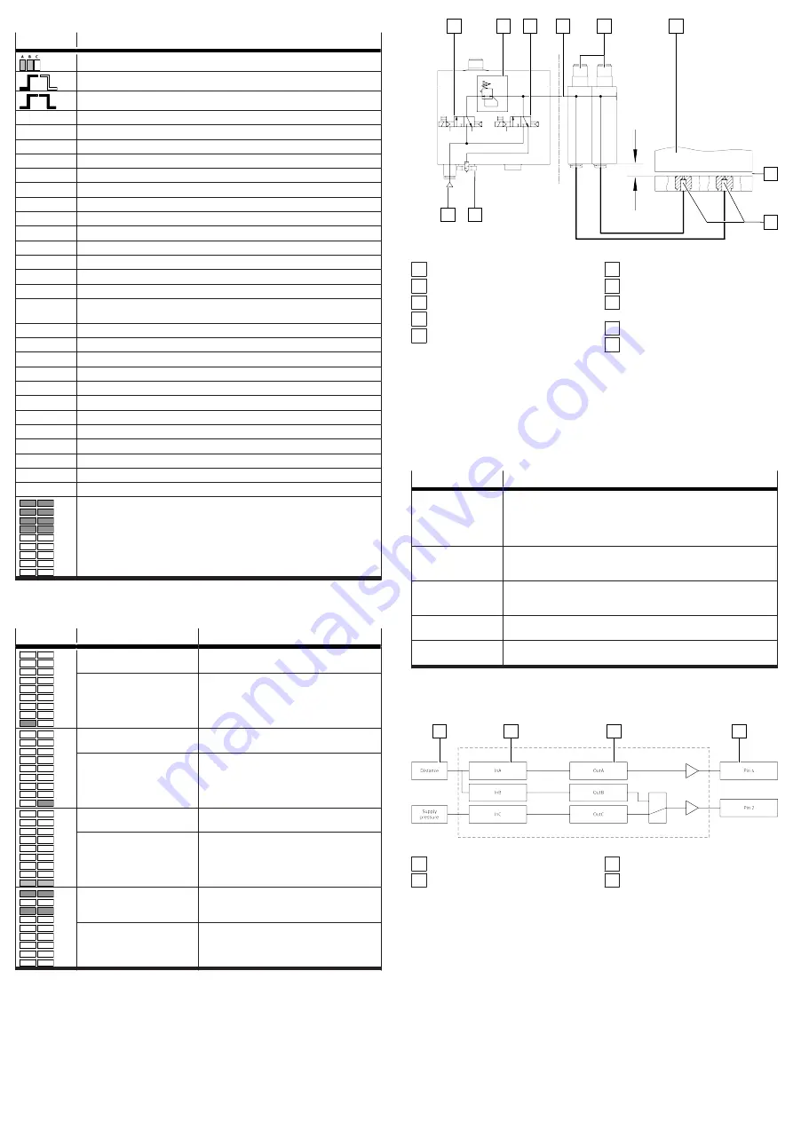
Functional Principle
The system consists of two sub-components. The control module provides a
compressed air preparation that is adapted to the supply pressure of the sensor
module, as well as the functionality for switching measuring and exhaust air. Up
to 4 sensor modules contain the sensory functions. The sensor modules can be
operated both individually and in combination with the control module.
1
2
3
4
5
6
7
8
9
10
Fig. 3: Configuration with a control module and two sensor modules
1 3/2-way valve (instrument air)
2 Pressure regulator
3 3/2-way valve (exhaust air)
4 Supply pressure
5 Sensor modules (pneumatically
linked)
6 Object (example)
7 Air gap
8 Measuring nozzles (1 per sensor
module)
9 Vent screw
10 Supply port for operating pres-
sure
The compressed air flows from the sensor modules to the measuring nozzles. If
the object is very close to a measuring nozzle, the air gap is very small and only
a small amount of air flows through. As the object gets further away, the air gap
becomes larger and more air flows through. The change in flow rate is detected
by the sensor modules, converted into a distance-correlated value and displayed
(speed measuring method with ejector).
4.2.2
Operating statuses
Operating status
Function
RUN mode
–
Basic status after the operating voltage is applied
–
Numerical and graphic display of distance-correlated values (bar
graph)
–
Display of measured values for supply pressure (in bar)
–
Display of the signal statuses of the binary signals OutA, OutB, OutC
INFO mode
–
Display of input variables in the display
–
Switch the display by pressing the A-pushbutton, B-pushbutton or A
and B-pushbuttons simultaneously.
SHOW mode
–
Display of current settings for the binary signals,
–
Display and reset of the min/max values for the correlating distance
value and the supply pressure
EDIT mode
–
Setting or alteration of the parameters for the air gap sensor (switching
outputs, display)
TEACH mode
–
Teaching of the switching points for the correlating distance values
(transfer of the current value as switching threshold)
Tab. 5: Operating statuses
4.2.3
Switching outputs
4.2.3.1 Switching signals
1
2
3
4
Fig. 4: Binary signals and switching signals SOPA-...-2P/2N-...
1 Sensing variable
2 Input signal
3 Binary signal
4 Switching signal at sensor module
plug


