background image

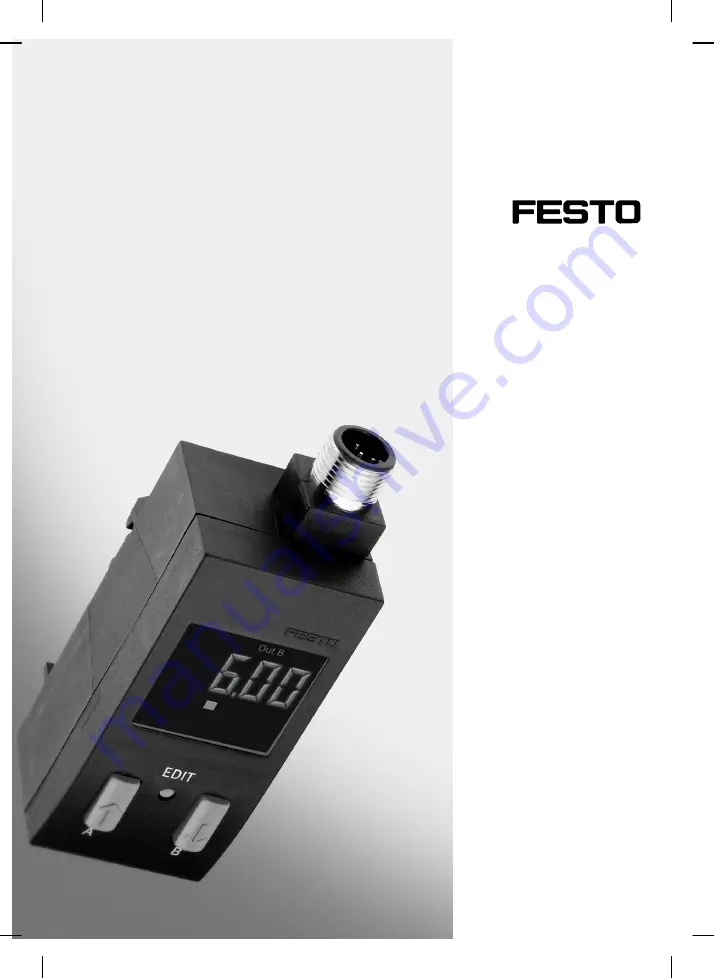
(de) Bedienungs−
anleitung

(en) Operating 
instructions

Drucksensor
Pressure  sensor

SDE1−...

689  940
0511e

US

 patent

 no

6,429,548

Содержание SDE1 Series

Страница 1: ... de Bedienungs anleitung en Operating instructions Drucksensor Pressure sensor SDE1 689 940 0511e US patent no 6 429 548 ...

Страница 2: ...alifi ziertem Fachpersonal gemäß Bedienungs anleitung Warnung Warning Caution Hinweis Please note Umwelt Antipollution Zubehör Accessories Fitting and commissioning to be carried out by qualified personnel only in accordance with the operating instructions Deutsch 3 English 33 ...

Страница 3: ...nd Anwendung 8 4 Voraussetzungen für den Produkteinsatz 8 5 Einbau 10 Mechanisch R14 R18 H W FQ4 10 Pneumatisch R14 R18 H W FQ4 11 Elektrisch 13 6 Inbetriebnahme 16 Symbolik auf dem Display 16 Inbetriebnahme Vorbereitung 18 Probelauf 23 7 Bedienung und Betrieb 24 8 Wartung und Pflege 24 9 Ausbau 25 10 Zubehör 25 11 Störungsbeseitigung 26 12 Technische Daten 27 13 Menüstruktur 29 ...

Страница 4: ...SDE1 Festo SDE1 0511e Deutsch 4 1 Bedienteile Anschlüsse und Varianten 1 2 3 4 5 6 7 9 aJ aA aB aD 2 aC 8 8 2 8 ...

Страница 5: ... Adapter zur Montage an Wartungsgeräte der MS6 Reihe 7 Adapter zur Montage an Wartungsgeräte der MS4 Reihe 8 Druck Vakuumanschluss oder öffnung auf der Unter oder Rückseite Ausführung abhängig vom Typ 9 Adapter mit Außengewinde zur Montage an Wartungsgeräte der MS oder D Reihe aJ DOWN Taste B aA EDIT Knopf aB UP Taste A aC Riegel zur Flanschbefestigung aD Schutzhaube optional Bild 1 ...

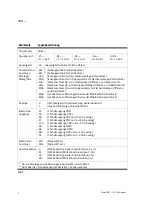
Страница 6: ...n der MS4 Reihe Relativdruck MS6 zur Adaption an Wartungseinheiten der MS6 Reihe Relativdruck Anzeige C LCD Anzeige mit Hinterleuchtung bedienoptimiert L Leucht LCD Anzeige ableseoptimiert Elektrische Ausgänge P1 1 Schaltausgang PNP P2 2 Schaltausgänge PNP PU 1 Schaltausgang PNP und 0 10 V analog PI 1 Schaltausgang PNP und 4 20 mA analog 2I 2 2 Schaltausgänge PNP und 4 20 mA analog N1 1 Schaltausg...

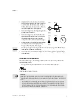
Страница 7: ... Sie Out B einstellen möchten B Taste DOWN drücken Out B blinkt 3 2 mal EDIT Knopf drücken SP Feld blinkt 4 Den gewünschten Schaltpunkt mit den Tasten UP DOWN einstellen 5 EDIT Knopf 3 s gedrückt halten Der SDE1 ist dann im RUN Modus So teachen Sie einen Schaltpunkt 1 Messdruck anlegen Relativdruck p1 Differenzdruck p1 p2 2 Um den Messwert als Teach Punkt TP1 für Out A zu übernehmen zuerst die A T...

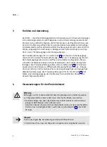
Страница 8: ...ch als Schwellwert oder Fenster Komparator festlegen Die Produktausführungen FQ4 HQ4 und WQ4 siehe Bild 2 bieten 2 pneumatische Anschlüsse zur Differenzdruckmessung Messdruck p1 Bezugs druck p2 Wird p2 nicht verschlaucht ist der Umgebungsdruck der Bezugsdruck Relativdruckmessung Die Produktausführungen PU PI NU NI siehe Bild 2 bieten einen Analogausgang der den Messwert als elektrisches druckpropo...

Страница 9: ...f stofflicher Basis Ausnahme Ölpapier Restmüll S Verwenden Sie den Artikel im Originalzustand ohne jegliche eigenmächtige Veränderung Einsatzbereich und Zulassungen Produktausführungen die mit folgendem Zeichen versehen sind erfüllen die Anforderungen nach Recognized Component Marks for Canada and the United States Only for use in Class 2 Circuits Hinweis Beachten Sie Folgendes wenn in Ihrem Einsa...

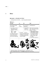
Страница 10: ...Nm Spannplatte gegen Fronttafel 1 SDE1 in die Aus sparung 85 5 x 36 mm R14 12 Nm R18 7 Nm Ein zusätzliches Abdich ten des PTFE beschich tetenAnschlussgewin des ist nicht notwendig S Den SDE1 in die Hut schiene oder Adapterplatte einhängenundandrücken bis der Befestigungsschie ber a einrastet sparung 85 5 x 36 mm der Fronttafel einführen Spannplatteeinhängen und andrücken bis der Befestigungsschieb...

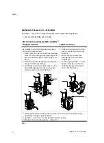
Страница 11: ...er R Gewinde G x Steckverschraubungenfür Differenzdruck S SDE1 auf Adapter stecken und mit Riegel sichern MaximalesAnzugsdrehmo ment 7 Nm S Anschlussverschraubung mit Dichtung eindrehen Alternativ über Doppel nippel E 1 8 1 8 1 Schlauch Außen Ø 4 mm in Steckverschrau bungeneinstecken 2 Auf korrekten Anschluss von p1 und p2 achten 1 1 Relativdruck p1 Differenzdruck p1 p2 Bild 6 ...

Страница 12: ...den Sitz der O Ringe und entfernen Sie ggf überflüssige O Ringe 3 Zur Montage die mit den Haltewinkeln verbun denen Befestigungsschrauben nach außen schieben und mit 0 5 Nm festziehen 3 1 Prüfen Sie den Sitz der Formdich tung c auf der Vorderseite des Adapters 2 Achten Sie auf saubere Dich tungsflächen zwischen SDE1 und Adapter 3 Zur Montage den SDE1 in den Adapter einsetzen andrücken und Befestig...

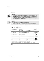
Страница 13: ...0204 1 Hinweis Lange Signalleitungen reduzieren die Störfestigkeit S Stellen Sie sicher dass die Signalleitungen stets kürzer sind als 30 m S Verkabeln Sie den SDE1 wie folgt SDE1 P1 N1 1 Ausgang Pin Kabelfarben 1 Belegung Stecker 2 3 polig M8 4 polig M12 1 braun BN DC 24 V Versorgungsspannung 3 polig M8 4 schwarz BK Ausgang A Out A 3 blau BU 0 V 4 polig M12 2 n c 1 Bei Verwendung der Anschlussdos...

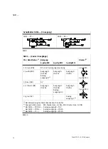
Страница 14: ...sgang B Out B Analog ausgang B 3 Ausgang A Out A Ausgang B Out B 4 polig M12 3 blau BU 0 V 4 schwarz BK Ausgang A Out A Ausgang B Out B Analog ausgang B 3 Ausgang A Out A 5 polig M12 5 grau GY Analog ausgang C 4 1 Bei Verwendung des Steckdosenkabels lt Zubehör 2 Anzugsdrehmoment M8 Stecker max 0 3 Nm M12 Stecker max 0 5 Nm 3 Bei SDE1 PU NU Analogausgang 0 10 V Bei SDE1 PI NI Analogausgang 4 20 mA ...

Страница 15: ...SDE1 Festo SDE1 0511e Deutsch 15 Schaltbilder SDE1 2 oder 3 Ausgänge SDE1 P2 SDE1 N2 SDE1 PU M8 SDE1 NU M8 SDE1 PU M12 SDE1 NU M12 SDE1 PI M8 SDE1 NI M8 SDE1 PI M12 SDE1 NI M12 SDE1 2I M12 Bild 11 ...

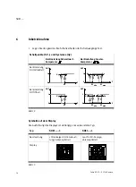
Страница 16: ...stellung Fenster Komparator BeiEinstellung NO Schließer P 1 0 Hy OUT SP Hy Hy P 1 0 OUT SP min SP max BeiEinstellung NC Öffner P 1 0 SP Hy OUT P 1 0 OUT SP min SP max Hy Hy Bild 12 Symbolik auf dem Display Die Ausführung des Displays ist abhängig vom verwendeten Typ Typ SDE1 C SDE1 L Beschreibung LCD Anzeige mit Hinterleuch tung bedienoptimiert Leucht LCD Anzeige ableseoptimiert Display Bild 13 ...

Страница 17: ...normally closed min Minimalwert Messdruck max Maximalwert Messdruck lock lock Sicherheitscode aktiv Sperrung gegen unbefugteProgrammierung Segmente leuchten Grafische Anzeige des aktuellenMesswerts bezogen auf den max Messwert des Messbereichs min max min und max bzw 2 Segmente blinken Minimal Maximalwert wird zurückgesetzt 3 Segmente blinken Hysteresewert wird angezeigt 1 Segment blinkt angezeigt...

Страница 18: ...Prüfen Sie die Funktionen des SDE1 Hinweis Eine Übersicht zur Menüstruktur finden Sie in Abschnitt 13 Beachten Sie dass nur die Produktausführungen P2 2I und N2 zwei Schaltausgänge Out A und Out B besitzen Andere Produktausführungen besitzen nur einen Schaltaus gang Out A RUN Modus Zeigt den Messwert Relativdruck Differenzdruck und den Signalzustand der Schaltausgänge Out A B an Ein blinkender Wer...

Страница 19: ...n erfolgt die Rückkehr in den RUN Modus S Drücken Sie mehrmals hintereinander die A Taste und prüfen Sie die aktuellen Werte und Einstellungen von Out A S Wenn Ihr SDE1 2 Schaltausgänge besitzt Drücken Sie mehrmals hinterein ander die B Taste und prüfen Sie auch die aktuellen Werte und Einstellungen von Out B EDIT Modus Der EDIT Modus ermöglicht folgende Einstellungen Schaltfunktion Schwellwert od...

Страница 20: ...ewählten Ausgangs EDIT Knopf drücken Die aktuell eingestellte Schaltfunktion blinkt 3 Gewünschte Schaltfunktion Schwellwert Fenster Komparator wählen mit UP DOWN Taste 4 Zur Bestätigung EDIT Knopf drücken SP bzw SP min blinkt SP bzw SP L wird kurz angezeigt Segment 5 blinkt 5 Schaltpunkt SP bzw SPmin einstellen mit UP DOWN Taste 6 Zur Bestätigung EDIT Knopf drücken Bei Schaltfunktion Fenster Kompa...

Страница 21: ...ut A blinkt 3 UP Taste drücken bis die Einheitenleiste gewählt ist lock kPA psi bar blinkt 4 Zur Bestätigung EDIT Knopf drücken Aktuelle Einheit kPA oder psi oder bar blinkt 5 Mit UP DOWN Taste die gewünschte Einheit wählen 6 Zur Bestätigung EDIT Knopf drücken lock blinkt 7 Gewünschten Sicherheitscode mit UP DOWN Taste einstellen 0 kein Schutz 8 Zur Bestätigung EDIT Knopf drücken Tipp Sicherheitsc...

Страница 22: ...TP2 Lage der Teach Punkte Beispiel Lage der Teach Punkte Beispiel Bild 16 Zum Teachen der Schaltgrößen 1 Ersten Messdruck anlegen Relativdruck p1 Differenzdruck p1 p2 2 Um den TEACH Modus zu aktivieren und den Messwert als ersten Teach Punkt TP1 zu übernehmen zuerst die Taste für den gewünschten Schaltausgang Out A B drücken dann bei gedrückter Taste den EDIT Knopf drücken 3 Nur bei aktiver Sicher...

Страница 23: ...asten A und B gleichzeitig Der bis zu diesem Zeitpunkt niedrigste Druckwert wird angezeigt min P Lo S Drücken Sie erneut die Tasten A und B gleichzeitig Der bis zu diesem Zeitpunkt maximale Druckwert wird angezeigt max P Hi S Drücken Sie erneut die Tasten A und B gleichzeitig Daraufhin erfolgt die Rückkehr in den RUN Modus Speicher Minimal Maximalwert zurücksetzen S A und B Taste gleichzeitig läng...

Страница 24: ...e aktuellen Einstellungen verloren S Notieren Sie bei Bedarf diese Einstellungen vor dem Rücksetzen Um den SDE1 auf Werkseinstellung zurückzusetzen 1 Schalten Sie die Betriebsspannung aus 2 Drücken Sie gleichzeitig alle drei Einstellelemente UP DOWN Taste und EDIT Knopf und schalten Sie dabei die Betriebsspannung wieder ein 8 Wartung und Pflege Zur Reinigung S Schalten Sie zur äußeren Reinigung fo...

Страница 25: ... Demontieren Sie den SDE 1 wie folgt SDE1 G2 MS Befestigungsschraube d lösen und SDE1 nach oben aus dem Adapter herausnehmen siehe auch Bild 7 SDE1 G2 R18 R14 SDE1 G2 H W SDE1 G2 FQ4 1 2 Bild 17 10 Zubehör Bezeichnung Typ Steckdosenkabel 3 polig M8 4 polig M8 3 polig M12 4 polig M12 5 polig M12 SIM M8 3 D SIM M8 4 D SIM M12 3 D SIM M12 4 D SIM M12 5 D Schutzhaube SDE1 SH Bild 18 ...

Страница 26: ...Anschlüsse vertauscht nur bei Q4 Verschlauchung gemäß Kapitel Einbau pneuma tisch ausführen SDE1 mit unzulässigem Mediumbetrieben SDE1 austauschen und nur mit Druckluft betreiben Druckanzeigeblinkt Überdruck im zulässigen Bereich Zul Druckbereich einhalten Überdruck über zul Maximal wert Gerät beschädigt SDE1 austauschen Ausgänge schalten nicht entsprechend der vorgenommenen Kurzschluss oder Überl...

Страница 27: ...0 5 40 0 040 1 996 0 000 1 800 0 999 0 996 0 000 1 800 0 020 0 998 0 000 0 900 Genauigkeit bei T 20 25 C bei T 0 50 C FS Schaltdrücke 2 Analogausgang 3 Schaltdrücke 3 Analogausgang 4 Wiederholbarkeit FS max 0 3 Kurzzeit Umgebungstemperatur Mediumstemperatur Lagertemperatur C C C 0 50 0 50 20 80 Betriebsspannungs bereich V DC 15 30 zul Restwelligkeit max 10 Leerlaufstrom mA Typ SDE1 C max 35 ca 30 ...

Страница 28: ...estigkeit Verpolungsschutz Taktend Für alle elektrischen Anschlüsse Schutzart IP65 nach EN 60529 Schutzklasse III nach DIN VDE 0106 1 Störfestigkeit Störaussendung Siehe Konformitätserklärung www festo com Siehe Konformitätserklärung www festo com Schwingungsfestigkeit Nach DIN IEC 68 EN 60068 Teil 2 6 0 35 mm Weg bei 10 60 Hz 5 g Beschleunigung bei 60 150 Hz Schockfestigkeit Nach DIN IEC 68 EN 60...

Страница 29: ...ckzukehren 3 SekundenEDIT Knopfdrücken Druck erzeugen zum Teachen des Messwertes hier TP1 Symbol auf dem Display blinkt hier Out B Sicherheitscode aktiv lock Sperrung gegen unbefugte Programmierung Sicherheitscode inaktiv lock Taste hier UP Taste drücken UP Taste A bzw DOWN Taste B erneut drücken UP Taste A und DOWN Taste B gleichzeitig drücken Taste hier UP Taste und EDIT Knopf gleichzeitig drück...

Страница 30: ...SDE1 Festo SDE1 0511e Deutsch 30 Bild 23 EDIT Modus ...

Страница 31: ...SDE1 Festo SDE1 0511e Deutsch 31 1 1 1 Nur bei Typ SDE1 L UP Taste A oder DOWN Taste B erneut drücken ...

Страница 32: ...SDE1 Festo SDE1 0511e Deutsch 32 Bild 24 TEACH Modus ...

Страница 33: ...application 38 4 Conditions of use 38 5 Installation 40 Mechanical R14 R18 H W FQ4 40 Pneumatic R14 R18 H W FQ4 41 Electrical installation 43 6 Commissioning 46 Symbols on the display 46 Preparing for commissioning 48 Test run 53 7 Operation 54 8 Care and maintenance 54 9 Dismantling 55 10 Accessories 55 11 Troubleshooting 56 12 Technical specifications 57 13 Menu structure 59 ...

Страница 34: ...SDE1 Festo SDE1 0511e English 34 1 Operating elements ports and variants 1 2 3 4 5 6 7 9 aJ aA aB aD 2 aC 8 8 2 8 ...

Страница 35: ...ingbracket 6 Adapter for mounting on MS6 series service units 7 Adapter for mounting on MS4 series service units 8 Pressure vacuum port or opening on the underside or rear side design depends on type 9 Adapter with male thread for mounting on MS or D series service units aJ DOWN button B aA EDIT button aB UP button A aC Latch for flange mounting aD Safety guard optional Fig 1 ...

Страница 36: ...ting to MS4 series service units relative pressure MS6 for adapting to MS6 series service units relative pressure Display C back lit LCD display optimised for use L illuminated LCD display optimised for reading Electrical outputs P1 1 PNP switching output P2 2 PNP switching outputs PU 1 PNP switching output and 0 10 V analog PI 1 PNP switching output and 4 20 mA analog 2I 2 2 PNP switching outputs...

Страница 37: ...the EDIT button twice SP field flashes 4 Set the desired switching point with the UP DOWN buttons 5 Hold the EDIT button pressed down for 3 s The SDE1 is then in the RUN mode You can teach a switching point as follows 1 Apply measuring pressure relative pressure p1 differential pressure p1 p2 2 In order to accept the measured value as the teaching point TP1 for Out A first press the A button then ...

Страница 38: ...parator or window comparator The product versions FQ4 HQ4 and WQ4 see Fig 2 provide two pneumatic ports for differen tial pressure measurement measuring pressure p1 reference pressure p2 If there is no tube connection for p2 the reference pressure is the ambient pressure relative pressure measurement The product versions PU PI NU NI see Fig 2 have an analog output which transfers the measured valu...

Страница 39: ...le waste S Use the product in its original state Unauthorised modification is not permitted Areas of application and official certifications Product versions showing the following symbol are compliant with the requirements of Recognized Component Marks for Canada and the United States Only for use in Class 2 Circuits Please note Note the following if compliance with the requirements of Recognized ...

Страница 40: ...imumtightening torque 0 5 Nm clamping plate against front panel 1 Guide SDE1 into the cut out 85 5 x 36 mm on R18 7 Nm Additional sealing of the PTFE coated connecting thread is not necessary S Attach the SDE1 onto the hat rail or adapter plate and press until the fastening slide a clips in cut out 85 5 x 36 mm on the front panel Attach the clamping plate and press until the fastening slide clips ...

Страница 41: ...read Gx Push in fittings for differential pressure S Push SDE1 onto adapter and secure it with the latch Maximumtightening torque 7 Nm S Screw in screwed joint with seal Alternative via double nipple E 1 8 1 8 1 Insert tubing outer dia 4 mm into push in fittings 2 Make sure that p1 and p2 are correctly connected 1 1 Relative pressure p1 differential pressure p1 p2 Fig 6 ...

Страница 42: ...irmly in place and remove any unnecessary O rings 3 To mount the unit push the mounting screws connected to the mounting brackets out wards and tighten to 0 5 Nm 3 1 Check that the moulded seal c on the front side of the adapter is firmly in place 2 Make sure the sealing surfaces between the SDE1 and the adapter are clean 3 To mount insert the SDE1 into the adapter press on it and tighten mounting...

Страница 43: ...Please note Long signal cables reduce the immunity to interference S Make sure that the signal cable is not longer than 30 m S Connect the SDE1 as follows SDE1 P1 N1 1 output Pin cable colours 1 Assignment Plug 2 3 pin M8 4 pin M12 1 brown BN 24 V DC power supply 3 pin M8 4 black BK Output A Out A 3 blue BU 0 V 4 pin M12 2 n c 1 Using the connection socket with cable as specified in the chapter Ac...

Страница 44: ...ut B ana log output B 3 Output A Out A Output B Out B 4 pin M12 3 blue BU 0 V 4 pin M12 4 black BK Output A Out A Output B Out B ana log output B 3 Output A Out A 5 pin M12 5 grey GY Analog output C 4 1 If using the cable with socket as specified in Accessories 2 Tightening torque M8 plug max 0 3 Nm M12 plug max 0 5 Nm 3 With SDE1 PU NU analog output 0 10 V With SDE1 PI NI analog output 4 20 mA 4 ...

Страница 45: ...SDE1 Festo SDE1 0511e English 45 Circuit diagrams for SDE1 2 or 3 outputs SDE1 P2 SDE1 N2 SDE1 PU M8 SDE1 NU M8 SDE1 PU M12 SDE1 NU M12 SDE1 PI M8 SDE1 NI M8 SDE1 PI M12 SDE1 NI M12 SDE1 2I M12 Fig 11 ...

Страница 46: ...rsetting With NO setting normally open contact P 1 0 Hy OUT SP Hy Hy P 1 0 OUT SP min SP max With NC setting normally closed contact P 1 0 SP Hy OUT P 1 0 OUT SP min SP max Hy Hy Fig 12 Symbols on the display The configuration of the display depends on the type used Type SDE1 C SDE1 L Description Back lit LCD display optimised for use Illuminated LCD display optimised for reading Display Fig 13 ...

Страница 47: ...min Minimummeasuringpressure max Maximum measuring pressure lock lock Security code active blocks unauthorised programming Segments light up graphic display of the current measured value in relation to the max measured value of the measuring range min max min and max or 2 segments flashing Minimum maximumvalue is being reset 3 segments flashing Hysteresis value is being displayed 1 segment flashin...

Страница 48: ...eck the functions of the SDE1 Please note An overview of the menu structure can be found in section 13 Note that only product versions P2 2I and N2 are equipped with two switching outputs Out A and Out B Other product versions have only one switching output Out A RUN mode Shows the measured value relative pressure differential pressure and the signal status of the switching outputs Out A B A flash...

Страница 49: ...O NC The program then returns to the RUN mode S Press the A button several times in succession and check the current values and settings of Out A S If your SDE1 has two switching outputs press the B button several times in succession and check the current values and settings of Out B as well EDIT mode The EDIT mode enables the following settings switching function threshold value or window compara...

Страница 50: ...DIT button The currently set switching function now flashes 3 Select desired switching function threshold value window comparator with the UP DOWN button 4 In order to confirm press the EDIT button SP or SP min flashes SP or SP L is shown briefly Segment 5 flashes 5 Set the switching point SP or SPmin with the UP DOWN button 6 In order to confirm press the EDIT button With window comparator switch...

Страница 51: ... A flashes 3 Press the UP button until the units bar is selected lock kPA psi bar flashes 4 In order to confirm press the EDIT button The current unit kPA or psi or bar flashes 5 Use the UP DOWN button to select the desired unit 6 In order to confirm press the EDIT button lock flashes 7 Set the desired security code with the UP DOWN button 0 no protection 8 In order to confirm press the EDIT butto...

Страница 52: ...example Fig 16 For teaching the switching variables 1 Apply first measuring pressure relative press p1 differential press p1 p2 2 In order to activate the TEACH mode and to accept the measured value as the first teaching point TP1 first press the button for the desired switching out put Out A B then press the EDIT button while holding down the switching output button 3 Only with active security bl...

Страница 53: ...ess buttons A and B simultaneously The lowest pressure value up to that moment will then be displayed min P Lo S Press buttons A and B again simultaneously The maximum pressure value up to that moment will then be displayed max P Hi S Press buttons A and B again simultaneously The unit then returns to the RUN mode Resetting the minimum maximum value memory S Hold the A and B buttons pressed down l...

Страница 54: ...set to the factory setting S If necessary make a note of these settings before a reset In order to reset the SDE1 to the factory setting 1 Switch off the operating voltage 2 Press all three setting controls simultaneously UP DOWN button and EDIT button and switch the operating voltage on again 8 Care and maintenance Cleaning S Switch off the following sources of energy before cleaning the exterior...

Страница 55: ...ions on the SDE1 S Dismantle the SDE1 as follows SDE1 G2 MS Undo mounting screw d and remove the SDE1 upwards out of the adapter see also Fig 7 SDE1 G2 R18 R14 SDE1 G2 H W SDE1 G2 FQ4 1 2 Fig 17 10 Accessories Designation Type Cable with socket 3 pin M8 4 pin M8 3 pin M12 4 pin M12 5 pin M12 SIM M8 3 D SIM M8 4 D SIM M12 3 D SIM M12 4 D SIM M12 5 D Safety guard SDE1 SH Fig 18 ...

Страница 56: ...tic connections swapped only with Q4 Connect tubing in accordance with the chapter Pneumatic installation SDE1 operated with non permittedmedium Replace the SDE1 and operate only with compressed air Pressure indicator flashes Excess pressure within permitted range Keep to permitted pressure range Excess pressure over maximum permitted value device damaged Replace SDE1 Outputs do not switch accordi...

Страница 57: ... 00 5 40 0 040 1 996 0 000 1 800 0 999 0 996 0 000 1 800 0 020 0 998 0 000 0 900 Accuracy at T 20 25 C at T 0 50 C FS Switching pressures 2 analog output 3 Switching pressures 3 analog output 4 Reproducibility FS max 0 3 short time Ambient temperature Media temperature Storage temperature C C C 0 50 0 50 20 80 Operating voltage range V DC 15 30 V DC permitted residual ripple max 10 Idle current mA...

Страница 58: ...t circuit Protect against polarity reversal Pulsed For all electrical connections Protection class IP65 as per EN 60529 Protection class III as per DIN VDE 0106 1 Interferenceimmunity Interference emission See declaration of conformity www festo com See declaration of conformity www festo com Vibration resistance As per DIN IEC 68 EN 60068 part 2 6 0 35 mm travel at 10 60 Hz 5 g accelerat at 60 15...

Страница 59: ... the EDIT button for 3 seconds Create pressure for teaching the measured value here TP1 Symbol on the display flashes here Out B Security code active lock blocked against unauthorised programming Security code inactive lock Press button here UP button Press UP button A or DOWN button B again Press UP button A and DOWN button B simultaneously Press the button here UP button and EDIT button simultan...

Страница 60: ...SDE1 Festo SDE1 0511e English 60 Fig 23 EDIT mode ...

Страница 61: ...SDE1 Festo SDE1 0511e English 61 1 1 1 Only with type SDE1 L press UP button A or DOWN button B again ...

Страница 62: ...SDE1 Festo SDE1 0511e English 62 Fig 24 TEACH mode ...

Страница 63: ...SDE1 Festo SDE1 0511e 63 de Lochbilder Adapterplatte en Hole pattern on adapter plate ...

Страница 64: ...n ou reproduction de ce document sous quelque forme que ce soit et toute exploitation ou communication de son contenu sont interdites sauf autorisation écrite expresse Tout manquement à cette règle est illicite et expose son auteur au versement de dommages et intérêts Tous droits réservés pour le cas de la délivrance d un brevet d un modèle d utilité ou d un modèle de présentation Copyright E Fest...

Отзывы: