background image

Prüfen Sie die Notwendigkeit zusätzli-
cher Bohrungen im Befestigungs-
flansch des FLSM-...

Mit den schraffierten Stellen in ne-
benstehender Zeichnung sind die Be-
reiche gekennzeichnet, in denen am
FLSM-... zusätzliche Bohrungen an-
gebracht werden können (z.B. zur
Aufnahme von Zentrierstiften).

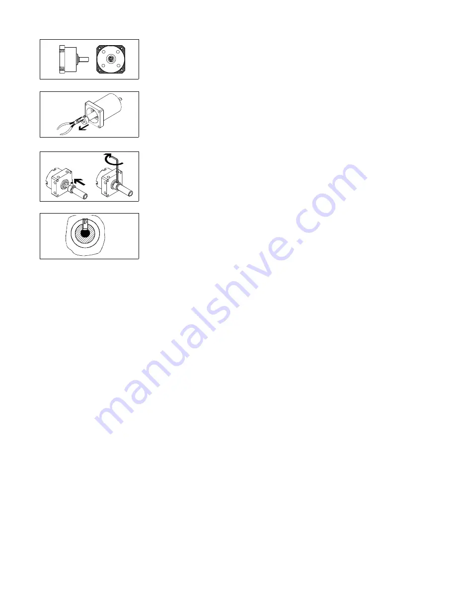
Zur Befestigung des Mitnehmers an der
Abtriebswelle des Antriebs (nur bei
FLSM-6-... und FLSM-8-...) vollziehen
Sie folgende Schritte:

1. Mitnehmer mit einer Zange aus dem

Freilauf ziehen (oder durch Aufstecken
und Verkanten der Abtriebswelle des
DSM-...)

2. Mitnehmer bis zum Anschlag auf die

Abtriebswelle schieben und Gewinde-
stift [SW 1,5] eindrehen. 
Dabei muß der Gewindestift auf der
Abflachung der Abtriebswelle senk-
recht aufsitzen.
Das Anziehdrehmoment beträgt 1 Nm.

3. Bei Bedarf: Gewindestift mit Loctite 243

gegen ungewolltes Lösen sichern.

Check whether there is a need for
additional holes in the mounting
flange of the FLSM-... 

The hatched areas in the adjacent
drawing designates the areas, where
additional holes are to be drilled on
the FLSM-... (e.g. for the retention of
centering pins).

In order to fasten the driver onto the
shaft of the drive (only with FLSM-6-...
and FLSM-8-...), carry out the following
steps:

1. Use pliers to pull the driver out of the

idle run (or by fixing and tilting the dri-
ve shaft).

2. Push the driver as far as it will go onto

the drive shaft and screw in a threa-
ded pin [A/F 1.5].
The threaded pin must sit vertically
the flat recess of the drive shaft.
 
The tightening torque is 1 Nm.

3. If required, use Loctite 243 to secure

the threaded pin against unintentional
loosening. 

Bild 5/Fig. 5

Bild 6/Fig. 6

Bild 7/Fig. 7

Bild 8/Fig. 8

0007a

D/GB 5

Содержание FLSM Series

Страница 1: ...M Einbau und Inbetriebnahme nur von autorisiertem Fachpersonal gemäß Bedienungsanleitung Fitting and commissioning to be carried out by qualified personnel only in accordance with the operating instructions Es bedeuten Symbols Warnung Warning Caution Hinweis Note Recycling Recycling Zubehör Accessories 397 980 0007a D GB 1 ...

Страница 2: ...des Schwenkantriebs DSM wird durch den Freilaufvorsatz nur in eine Richtung ausgeführt FLSM R Rechtslauf im Uhrzeigersinn FLSM L Linkslauf im Gegenuhrzeigersinn bei Blickrichtung auf Abtriebswelle Die andere Richtung ist gesperrt Es resultiert eine getaktete gleichförmi ge Schrittbewegung Es lassen sich stu fenlos einstellbare Taktvorschübe erzie len Function and application The bidirectional rota...

Страница 3: ...itung des Antriebs DSM einschränken Berücksichtigen Sie immer die enge re Werteangabe The FLSM idle run is only intended for use in conjunction with a swivel drive of type DSM for step by step moving of work loads on a circular path Prerequisites for product application PLEASE NOTE Incorrect handling can lead to malfunction ing Observe the instructions and specifi cations in the operating instruct...

Страница 4: ...chanisch Behandeln Sie den FLSM so daß keine Schäden an der Abtriebswelle auftreten Observe all warnings and notes on the product in these operating instructions Use the product in its standard form without any unauthorised modificati ons Transport and storage Take into account the weight of the FLSM This can be up to 2 35 kg Installation Mechanical Handle the FLSM carefully so as to prevent any d...

Страница 5: ...nziehdrehmoment beträgt 1 Nm 3 Bei Bedarf Gewindestift mit Loctite 243 gegen ungewolltes Lösen sichern Check whether there is a need for additional holes in the mounting flange of the FLSM The hatched areas in the adjacent drawing designates the areas where additional holes are to be drilled on the FLSM e g for the retention of centering pins In order to fasten the driver onto the shaft of the dri...

Страница 6: ...Stellen Sie sicher dass die bewegli che Masse bei Überschreiten des oberen Totpunktes nicht nach unten schlägt externe Sicherung gegen Durchschlagen z B getaktete Zylin der verwenden For eccentric loads moved in vertical di rection PLEASE NOTE There is no overrun blocking in the di rection of rotation If the upper top dead centre is exceeded the mass will be ac celerated additionally by its force ...

Страница 7: ...mit selbstge fertigtem Schutzgitter Make sure that the following specifi cations are observed when posi tioning the moving load see techni cal data clearance around adjacent parts permissible axial force permissible radial force Make sure that the moving mass can not slide off the drive shaft This can be achieved with the following de pending on the size of the drive shaft the flat recess the thre...

Страница 8: ... weglichen Masse sowie das Dämp fungsverhalten des Anschlags sollte be rechnet worden sein If external stops and shock absorbers are used make sure that the following specifica tions are observed the impact point in the mass centre of gravity S important with eccentric masses m on the lever arm the maximum permitted impact force the minimum impact radius rmin see Technical specifications Take the ...

Страница 9: ...paratur zu Festo ein Zubehör Operation and control If the working load is changed Observe the permissible loads Service and maintenance If necessary Clean the FLSM externally with a soft cloth Permissible cleaning agent Soap suds max 60 C Disassembly and repairs Send the defective FLSM to Festo for repairs Accesoires 8 9 10 Bezeichnung Typ Fett K2E 30 nach DIN 51825 Aufsteckflansch FWSR Bild 16 De...

Страница 10: ...mm 6 7 N 9 5 N 24 3 N 340 N 220 N 450 N 40 mm 5 7 N 8 1 N 20 7 N 200 N 400 N 50 mm 4 9 N 7 N 18 N 350 N Mindestradius r min für Anschlagpunkt 10 mm 12 mm 13 5 mm siehe Bedienungsanleitung des Schwenkantriebs DSM zulässige Anschlagskraft Fx in abh vom Achsenabstand x 0 mm 20 N 36 N 72 8 N 280 N 530 N 650 N 1100 N 1400 N 10 mm 14 2 N 26 3 N 53 1 N 200 N 420 N 530 N 880 N 1150 N 20 mm 11 N 20 7 N 41 ...

Страница 11: ...500 N 30 mm 6 7 N 9 5 N 24 3 N 340 N 220 N 450 N 40 mm 5 7 N 8 1 N 20 7 N 200 N 400 N 50 mm 4 9 N 7 N 18 N 350 N Min radius r min for point of impact 10 mm 12 mm 13 5 mm see operating instructions of swivel actuator DSM Nominal size permissible stop force Fx in relation to axis distance x 0 mm 20 N 36 N 72 8 N 280 N 530 N 650 N 1100 N 1400 N 10 mm 14 2 N 26 3 N 53 1 N 200 N 420 N 530 N 880 N 1150 ...

Страница 12: ... held liable for the payment of damages All rights reser ved in particular the right to carry out patent utility model or ornamental de sign registrations Störung mögliche Ursache Abhilfe Ungleichförmige Bewe gung der beweglichen Masse zu große Masse Drehgeschwindigkeit am Schwenkantrieb reduzieren Durchdrehen des Freilaufs Gewindestift am Mitnehmer gelöst nur bei FLSM 6 und FLSM 8 Mitnehmer gemäß...

Отзывы: