


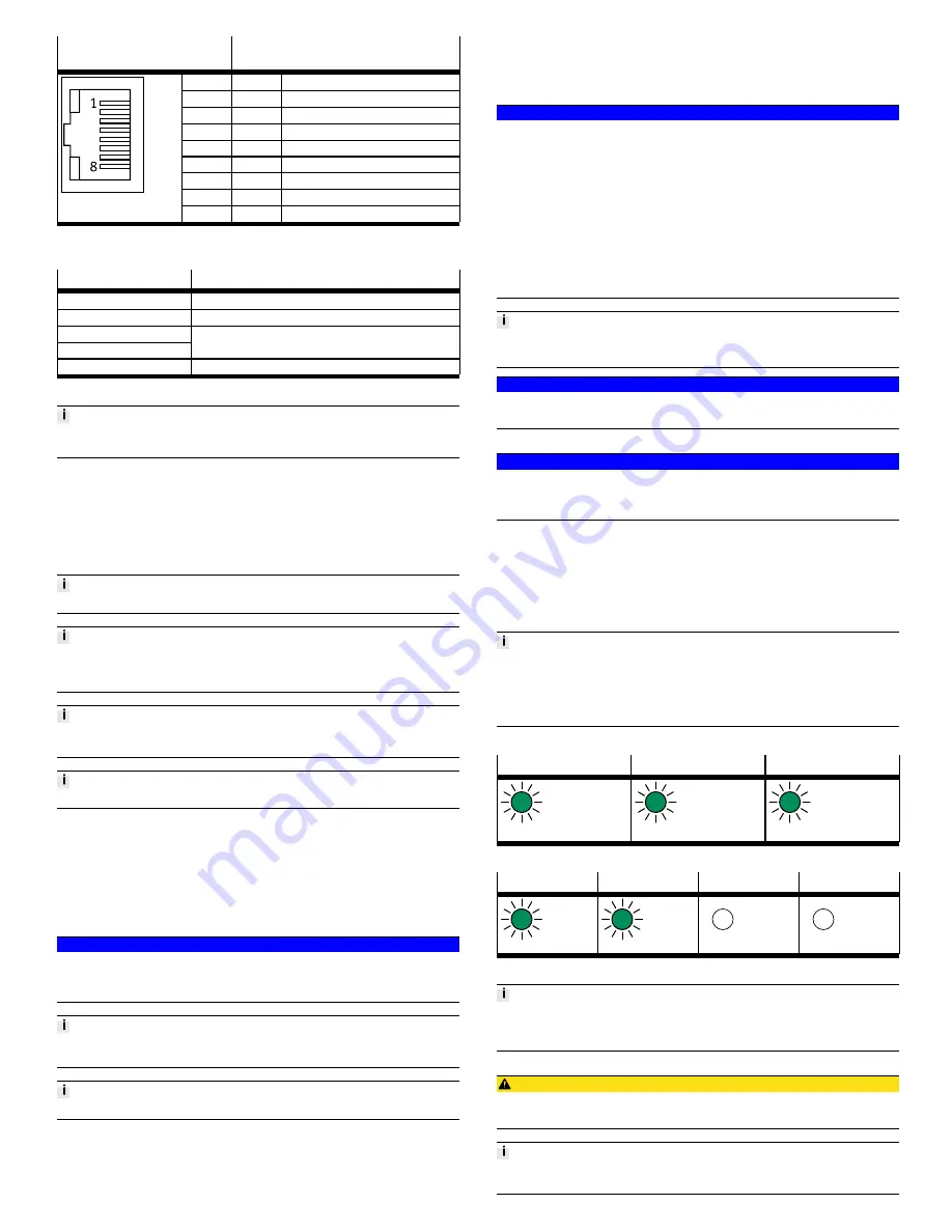
5.2.4.2 Network connections
Port [XF1], [XF2], [ETH1], [ETH2],
[EC]
Signal
1
TD+
Transmitted data +
2
TD–
Transmitted data –
3
RD+
Received data +
4
n.c.
–
5
n.c.
–
6
RD–
Received data –
7
n.c.
–
8
n.c.
–
1)
Shield
Functional earth
1) Housing
Tab. 7 Port [XF1], [XF2], [ETH1], [ETH2], [EC]
Connection
Function
[XF1]
EtherNet/IP Port 1
[XF2]
EtherNet/IP Port 2
[ETH1]
[ETH2]
Ethernet interfaces for the connection of a programming device,
PC or operating unit CDPX
[EC]
EtherCAT Master
Tab. 8 Network connections
The network connections ETH1 and ETH2 are connected to the controller via a
switch.
5.2.4.3 Memory card slot [Card]
The slot is used to save data and results to a memory card CAMC-M-MS-G32.
–
The data are saved in the directory /mnt/sdcard.
–
The data are accessed through SysFile and CAA.File
è
CODESYS libraries.
Requirements:
–
Maximum memory size: 32 GB
–
Formatting: FAT32 (one partition only)
When using a memory card, please note the direction and orientation.
Use only memory cards that are sold by Festo as accessories for the product
è
www.festo.com/catalogue.
Festo does not provide any warranty for the use of other memory cards.
The memory card slot is only intended for user-monitored operation.
•
Do not use memory cards for continuous data recording.
Memory cards cannot be used to execute CODESYS boot projects.
5.2.4.4 USB interface [USB]
The USB interface (A-coded socket, USB specification 2.0) is used to save data
and results to external storage media.
–
The data from the USB memory are saved in the directory /mnt/usb.
–
The data are accessed through SysFile and CAA.File
è
CODESYS libraries.
Requirements:
–
Maximum memory size: 32 GB
–
Formatting: FAT32 (one partition only)
NOTICE!
Impermissible operating states of the controller result from high current con-
sumption at the USB interface.
•
Use only storage media with a current consumption of
£
0.5 A.
The USB interface is only intended for user-monitored operation.
•
Do not use storage media for continuous data recording.
USB storage devices cannot be used to execute CODESYS boot projects.
6
Transport and storage
•
Observe specifications for environmental and storage conditions
è
13 Technical data.
7
Assembly
•
Assemble the module as outlined in the “Instruction manual for automation
system CPX-E”
è
1.1 Further applicable documents.
8
Installation
8.1
Network
NOTICE!
Unauthorised access to the device can cause damage or malfunctions.
When connecting the device to a network, protect the network from unauthorised
access.
Measures to protect the network include:
•
Firewall
•
Intrusion prevention system (IPS)
•
Network segmentation
•
Virtual LAN (VLAN)
•
Virtual private network (VPN)
•
Security at physical access level (port security)
Further information
è
Directives and standards for security in information tech-
nology, e.g. IEC 62443, ISO/IEC 27001.
Network
An access password only protects against unintentional modification.
NOTICE!
Transmission errors due to faulty installation or excessive transmission rates.
•
Please note the line specifications in the documentation of the controller.
8.2
Operating voltage supply U
EL/SEN
NOTICE!
Malfunction due to faulty installation.
•
Please note the information regarding the line specification, power supply
and earthing measures.
1. Please note the information in the “Instruction manual for automation system
CPX-E”
è
1.1 Further applicable documents.
2. Make sure that the power supply is switched off.
3. Connect the lines to the terminal strip in accordance with the “Instruction
manual for automation system CPX-E”
è
1.1 Further applicable documents.
9
Commissioning
You can find information on commissioning the automation system CPX-E in the
“Instruction manual for automation system CPX-E”.
You can find information on the parameters in the “Description of
automation system CPX-E” and in the descriptions of the modules used
è
1.1 Further applicable documents.
9.1
Behaviour of the display components after error-free commissioning
[MS] (green)
[NS] (green)
[XF1], [XF2] (green)
Lit
Lit
Lit or flashing
Tab. 9 Display components after error-free commissioning
[PS] (green)
[PL] (green)
[SF] (red)
[M] (yellow)
Lit
Lit
Off
Off
Tab. 10 Display components after error-free commissioning
You can find information on troubleshooting in the event of incorrect behaviour in
the “Description of automation system CPX-E” and the descriptions of the mod-
ules used
è
1.1 Further applicable documents.
9.2
Commissioning with CODESYS
CAUTION!
Risk of injury due to uncontrolled movements of the connected actuators.
•
Perform test runs of projects and applications without active actuators first.
•
For the configuration, parameterisation and programming of the product, use
CODESYS V3.


