


4. Clean the shaft of the motor
1
.
The coupling will only grip without slipping on a shaft pin which is dry and free of
grease.
If fat solvent media enters the bearing, it will wash out the service life lubrica-
tion of the bearing.
Note
Encoder and brake can be destroyed.
• Do not exceed the maximum axial shaft load (
Technical Data).
5. Place the EMMS-ST on the motor flange
2
.
6. Connect the motor to the mechanical components at the threaded holes
3
.
Ready to use motor kits for drives can be found in the Festo accessories
(
Accessories).
7. Tighten the fastening screws (
Instructions on drive and motor kits).
5
Commissioning
Note
The actuators connected to the motor can be started unexpectedly when the
holding brake is energised.
• Make sure that the motor is held to a controlled position by the controller
when the holding brake is energised/released.
• Complete the commissioning of the motor in conjunction with the controller in
accordance with the controller manual.
6
Operation
Warning
Hot parts of the housing can cause burning.
• Make sure that people and objects cannot come into direct contact with the
motor.
7
Maintenance and care
Warning
Layers of dust can catch fire.
• Clean the motor housing of dust regularly.
8
Disassembly and repair
Warning
Masses which suddenly slide down may cause injury to people.
• Make sure that the work load on the drive is in a safe position (e.g. in the case
of a vertical drive: in the lower end position).
• You can now remove the EMMS-ST from the mechanical components.
If repairs are required:
• return the motor to Festo.
Repairs by Festo will maintain the safety standards.
• Complete the fitting as follows:
1. Push the slide or the cantilever of the driven mechanical components into a safe
position.
2. Fit the motor kits in accordance with the specifications in the assembly instruc-
tions.
9
Accessories
Note
• Please select the accessories you need from our catalogue
(
www.festo.com/catalogue).
10
Troubleshooting
Malfunction
Possible cause
Remedy
Motor shaft does not turn
Load too high
Reduce motor load
Motor shaft does not turn
Controller has not yet been
enabled
Check controller signals
Holding brake active (only
with EMMS-ST-…-SB/-SEB)
Release holding brake
Motor shaft rotates in the
wrong direction
Cabling fault
Check cabling
Motor stops at wrong position
Stepper fault
Repeat reference run
Fig. 4
11
Technical data
EMMS-ST-28-L-…
S
SE
SB
SEB
Nominal motor operating voltage
[V]
48
Nominal motor current
[A]
1.4
Motor holding torque
[Nm]
0.09
Step angle with full step
[°]
1.8 ± 5 %
Winding resistance
[Ω]
2.3 ± 15 %
Winding inductance at 1 kHz
[mH]
1.4 ± 20 %
Total moment of inertia of drive
output
[kgcm
2
]
0.018
0.025
Brake operating voltage
[V]
–
24
Brake power consumption
[W]
–
8
Brake holding torque
[Nm]
–
0.2
Brake response delay
[ms]
–
6
Brake separation time
[ms]
–
10
Pulses / revolution
–
500
–
500
Zero pulse
–
Yes
–
Yes
Line driver (RS422 protocol)
–
Yes
–
Yes
Operating voltage of encoder
[V]
–
5
–
5
Radial shaft load:
5 mm distance from flange
[N]
58
20 mm distance from flange
[N]
20
Axial shaft load
[N]
7
Insulation protection class
B (130 °C)
IP protection (when installed)
IP65
Ambient temperature
[°C]
–10 … +50
CE mark (see declaration of conformity)
1)
To EU EMC Directive
Relative air humidity
(non-condensing)
[%]
45 … 80
Max. cable length
[m]
15 (see documentation for controller)
Product weight
[kg]
0.32
0.38
1)
Measures may need to be implemented in residential areas for interference suppression
Fig. 5
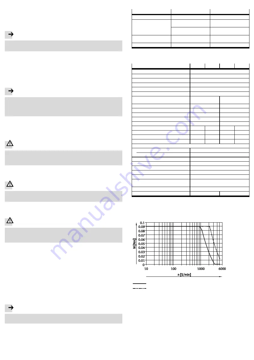
12
Characteristic curves
Rated voltage 48 V
24 V DC
48 V DC
Fig. 6


