


43
START-UP
General Rules
The following operations must be carried out only by properly trained personnel. To make the
contractual warranty
effective, start up
must be carried out by autho-
rized service centres
.
Before calling the service centre it is advisable to make sure that all the installation steps have been completed (positioning, electrical connections, hydraulic connections).
Preliminary Operations
WARNING - Before you perform the checks listed below, please read
carefully the section “Safety and Maintenance”
Verify
that :
- the unit has not suffered visible damages due to transport or positio-
ning
- the unit is placed on an horizontal surface able to bear its weight
- the minimum operating area are respected
- the ambient conditions comply with the provided operating limits
- the hydraulic and electrical connections has been carried out correctly
Electrical cheks
Verify that the unit power supply line complies with the regulations in force.
Check that the section of power cables are suitable to withstand the ove-
rall absorption of the unit (see electrical data), and that the unit has been
properly grounded.
Check that all electrical connections are well fixed and all terminals pro-
perly tightened.
Switch on the unit by turning the switch in position ON . The display will
light a few seconds after power up , check the operating status of both Std
-by or off ( via keyboard). A wrong sequence of the power supply phases
is immediately detected by the phase sequence controller (standard on all
the three phase power supply units) and reported on the display of the unit.
To eliminate the error switch each other two phases of the power supply
line.
Verify that:
- the voltage of the power supply line complies with the the nominal one
of the unit
- for three phase power supply units, the unbalance between the phases
is lower than 3% (a higher value produces an excesive current input
on one or more phases causing possible damages to the electrical
components of the unit)
NOTE
.
Example of phase unbalance calculation
- Read the value of the three line voltages using a voltmeter :
line voltage between phases L
1
and L
2
:
V
1-2
= 390 V
line voltage between phases L
2
and L
3
:
V
2-3
= 397 V
line voltage between phases L
3
and L
1
:
V
3-1
= 395 V
- Calculate the difference between the maximum and minimum value of the
measured line voltages :
ΔV
max
= max ( V
1-2
; V
2-3
; V
3-1
) - min ( V
1-2
; V
2-3
; V
3-1
) = V
2-3
- V
1-2
= 397 - 390 = 7 V
- Calculate the average line voltage value :
Δ
average
= ( V
1-2
+ V
2-3
+ V
3-1
) / 3 = ( 390 + 397 + 395 ) / 3 = 394 V
- Calculate the percentage unbalance value :
ΔV
max
/ V
average
x 100 = 7 / 394 x 100 = 1,78 % < 2 %
Check that the connections made by the installer comply with the data
reported here .
If present, check that the resistance of the compressors oil crankase are
operating, by measuring the temperature rise of the oil crankase. The re-
sistance / s must be in operation for at least 24 hours before starting the
compressor , and in each case the temperature of the oil crankase must be
10 - 15 ° C higher than the ambient temperature .
WARNING - At least 24 hours prior to the operation of the unit ( or at the
end of each period of prolonged pause ) the unit must be powered in such
a way as to allow the heating elements of the compressor crankcases to
evaporate the refrigerant present in the oil. Failure to do so may cause
serious damage to the compressor and will void the warranty.
Hydraulic circuit checks
Check that all hydraulic connections are executed correctly: Refer to the
installation manual.
Check that the hydraulic system is filled, under pressure and air free (pos-
sibly vent it).
Make sure that any shutoff valves present in the system are properly open.
Make sure that the circulation pump is running and that the water flow
is sufficient to close the contact of the differential pressure and / or flow
switches .
Check the correct operation of the differential pressure and / or flow
switches: close the shutoff valve at the outlet of the heat exchanger, the
unit display must show the alarm message, eventually reopen the valve
and reset the alarm.
Turning on
ATTENTION
. The operation must be agreed in advance depending on
the timing of construction of the plant . Before the intervention of Service
Department all works (electrical and plumbing connections , water filling
and air vent of the plant) will have been completed.
Start all the plant components necessary to guarantee an adequate water
flow rate on the plant hydraulic circuit.
Activate the unit in cooling or in heating mode operating on the user interfa-
ce and setting a set point suitable to require the unit to work.
Refrigerant circuit checks
The vibrations during transport , may have loose connections : check for le-
aks of refrigerant gas especially at the refrigerant pressure taps , pressure
transducers and pressure switches.
After a short period of operation, check the oil level of the compressor ( if
present siight oil) and the absence of bubbles in the glass of liquid indicator
( if present) . The continuous passage of vapor bubbles may mean that the
refrigerant charge is low or that the expansion valve is not properly adju-
sted. The presence of bubbles in the running for short periods , however,
is possible.
Evaporation and condensation temperature
Verify that:
- the saturation temperature (dew point) corresponding to the conden-
sing pressure is about 10-15°C higher than the outdoor air temperatu-
re in cooling and about 5°C higher than the water outlet temperature in
heating
- the saturation temperature (dew point) corresponding to the evapora-
ting pressure is about 5°C lower than the water outlet temperature in
cooling and about 5-10°C lower than the outdoor air temperature in
heating
Superheat
Check the superheat comparing the temperature measured with a con-
tact thermostat fitted to the compressor suction pipe , with the temperature
shown on the low pressure gauge ( saturation temperature corresponding
to the evaporation pressure ) . The difference between these two tempe-
ratures gives the value of the superheta. The optimal values are between
4 and 8 ° C.
Subcooling
Check the subcooling comparing the temperature measured with a con-
tact thermostat on the pipe outlet of the condenser , with the temperature
shown on the pressure gauge of high pressure ( saturation temperature
corresponding to the condensation pressure ) . The difference between
these two temperatures gives the value of subcooling . The optimal values
are between 4 and 5 ° C, for reversible units with subcooler in the coil the
optimal values are between 10 and 20 ° C depending on the external air
temperature .
Discharge temperature
If the values of subcooling and superheat are regular, the temperature me-
asured at the outlet of the compressor discharge pipe must be:
- Units charged with R410A of 30/40 ° C higher than the condensing tem-
perature
- Units charged with R134a of 15/20 ° C higher than the condensing tem-
perature .
Hydraulic circuit check
- the difference between the water inlet and outlet temperature from the
plate heat exchanger of the unit is inside the limits provided.
Electrical setting check
- the current absorbed by the compresor and the fans is lower than the
maximum value admitted (FLA), as indicated in the section “Technical
data and performances”
SAFETY AND MAINTENANCE
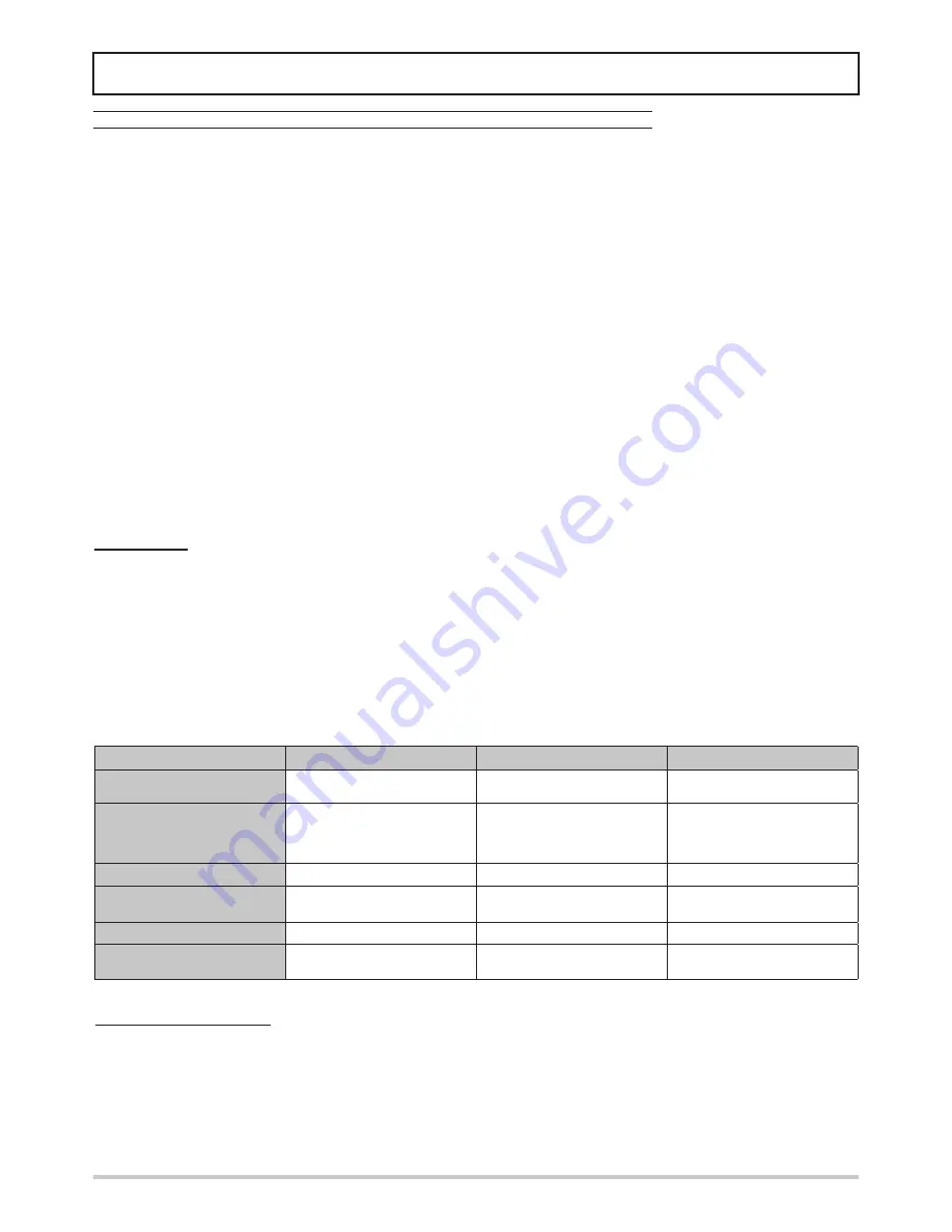
Part in question
Residue hazard
Mode
Precautions
Compressor and delivery
pipe
Burns
Contact with the pipes and/or com-
pressor
Avoid contact by wearing
protective gloves
Delivery pipes, heat recovery
exchanger and coils
Explosion
Excessive pressure
Turn off the machine,
check the high pressure switch
and safety valve,
the fans and condenser
Pipes in general
Ice burns
Leaking refrigerant
Do not pull on the pipes
Electrical cables, metal parts
Electrocution, serious burns
Defective cable insulation, live metal
parts
Adequate electrical protection (cor-
rectly ground the unit)
Heat exchange coils
Cuts
Contact
Wear protective gloves
Fans
Cuts
Contact with the skin
Do not push the hands or objects
through the fan grille
SAFETY AND MAINTENANCE
Basic safety rules
Recall that the use of products that use electricity and water entails the observance of some basic safety rules , such as: This applian-
ce is not intended for use by persons ( including children) with reduced physical , sensory or mental capabilities or lack of experience
and knowledge, unless supervised or instructed on the use of the appliance by a person responsible for their safety . Children should
be supervised to ensure that they do not play with the appliance.
It is forbidden to any technical intervention or maintenance without first disconnecting the unit from the mains supply by moving the
master switch and the main control panel to “Off” .
You may not modify safety equipment or settings.
Do not pull, detach or twist the electrical cables coming from the unit even if it is disconnected from the mains supply.
It is forbidden to leave containers of flammable substances near the unit.
Do not touch the appliance when barefoot or with wet or damp parts of the body .
It is forbidden to open the doors of access to the internal parts of the unit without first ensuring that the system switch to “Off”.
Not dispose of, abandon or leave within reach of children packaging materials as it can be a potential source of danger.
IMPORTANT SAFETY INFORMATION
There is no guarantee proper operation as a result of a fire, before restarting the machine, contact an authorized service center. If
equipped with safety valves refrigerant, in case of excessive pressure the safety valves can discharge high temperature refrigerant
gas to the atmosphere. Wind, earthquakes and other natural phenomena of exceptional intensity were not considered. When using
the unit in an aggressive atmosphere and or with aggressive water consult the factory.
Residual Risks
The machine has been designed with a view to reducing the risks to persons and the environment in which it is installed, to the
minimum. To eliminate residual risks, it is therefore advisable to become as familiar as possible with the machine in order to avoid
accidents that could cause injuries to persons and/or damage to property.
a . Access to the unit
Only qualified persons who are familiar with this type of machine and who are equipped with the necessary safety protections (fo-
otwear, gloves, helmet, etc.) may be allowed to access the machine. Moreover, in order to operate, these persons must have been
authorized by the owner of the machine and be recognized by the actual Manufacturer.
b . Elements of risk
The machine has been designed and built so as not to create any condition of risk. However, residual risks are impossible to eliminate
during the designing phase and are therefore listed in the following table along with the instructions about how to neutralize them.
Disconnection and disposal
The machine contains lubricating oil and refrigerant gas for which, during the destruction of the unit, these fluids will be recovered and
disposed of in accordance with the rules in force in the country where it is installed.
During the disconnection thus avoid spills or leaks of refrigerant gas and of the plant water if treated with additives or antifreeze
substances.
The machine must not be abandoned in the process of destruction, but it can also be stored outdoors with gas, water and electrical
circuits intact and closed.
For dismissing and disposal, deliver the units to specialized centres according to your national laws.
Basic safety rules