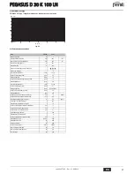


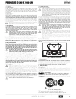


PEGASUS D 30 K 100 LN
35
EN
EN
1. GENERAL INSTRUCTIONS
•
Carefully read the instructions contained in this instruction booklet.
•
After boiler installation, inform the user regarding its operation and give him this
manual, which is an integral and essential part of the product and must be kept with
care for future reference.
•
Installation and maintenance must be carried out by professionally qualified person-
nel, according to current regulations and the manufacturer's instructions. Do not car-
ry out any operation on the sealed control parts.
•
Incorrect installation or inadequate maintenance can result in damage or injury. The
Manufacturer declines any liability for damage due to errors in installation and use
or failure to follow the instructions.
•
Before carrying out any cleaning or maintenance operation, disconnect the unit from
the power supply using the system switch and/or the special cut-off devices.
•
In case of a fault and/or poor operation, deactivate the unit and do not attempt to
repair it or directly intervene. Contact professionally qualified personnel. Repair/re-
placement of the products must only be carried out by professionally qualified using
original spare parts. Failure to comply with the above could affect the safety of the
unit.
•
This unit must only be used for its intended purpose. Any other use is considered
improper and therefore dangerous.
•
The packing materials are potentially hazardous and must not be left within the
reach of children.
•
The images given in this manual are a simplified representation of the product. In
this representation there may be slight and insignificant differences with respect to
the product supplied.
2. OPERATING INSTRUCTIONS
2.1 Introduction
Dear Customer,
Thank you for choosing
PEGASUS D 30 K 100 LN
, a floor-standing boiler
FERROLI
fea-
turing advanced design, cutting-edge technology, high reliability and quality construc-
tion. Please read this manual carefully and keep it for future reference.
PEGASUS D 30 K 100 LN
is a high-efficiency, low emissions
heat generator for heat-
ing and domestic hot water production
running on natural gas or LPG, regulated by
an advanced electronic control system,
The boiler shell consists of cast-iron elements whose particular shape guarantees high
exchange efficiency in all operating conditions, and an open-flue burner with electronic
ignition and ionisation flame control.
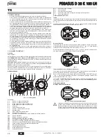
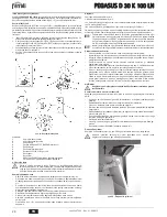
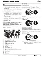
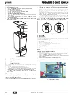
2.2 Control panel
fig. 1 - Control panel
Key
1 =
DHW temperature setting decrease button
2 =
DHW temperature setting increase button
3 =
Heating system temperature setting decrease button
4 =
Heating system temperature setting increase button
5 =
Display
6 =
Summer/Winter mode selection button
7 =
Economy / Comfort mode selection button
8 =
Reset button
9 =
Unit On / Off button
10 =
"Sliding Temperature" menu button
11 =
Set DHW temperature reached
12 =
DHW symbol
13 =
DHW mode
14 =
DHW outlet temperature / setting
15 =
Eco (Economy) or Comfort mode
16 =
External sensor temperature (with optional external probe)
17 =
Appears on connecting the external probe or the Remote Timer Control (option-
als)
18 =
Room temperature (with optional Remote Timer Control)
19 =
Burner On
20 =
Antifreeze operation
21 =
Heating system pressure
22 =
Fault
23 =
Heating delivery temperature / setting
24 =
Heating symbol
25 =
Heating mode
26 =
Set heating delivery temperature reached
27 =
Summer mode
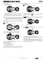
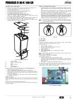
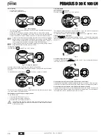
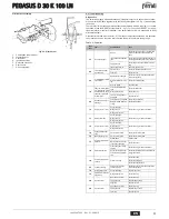
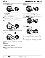
Indication during operation
Heating
A heating demand (generated by the Room Thermostat or Remote Timer Control) is in-
dicated by flashing of the hot air above the radiator (details 24 and 25 - fig. 1).
The heating graduation marks (detail 26 - fig. 1) light up as the heating sensor tempera-
ture reaches the set value.
fig. 2
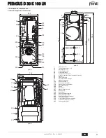
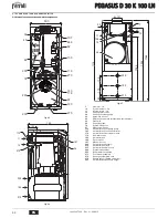
DHW (Comfort)
A DHW demand (generated by drawing domestic hot water) is indicated by flashing of
the hot water under the tap (details 12 and 13 - fig. 1). Make sure the Comfort function
(detail 15 - fig. 1) is activated.
The DHW graduation marks (detail 11 - fig. 1) light up as the DHW sensor temperature
reaches the set value.
fig. 3
Exclude hot water storage tank (economy)
Hot water tank temperature maintaining/heating can be excluded by the user. If exclud-
ed, domestic hot water will not be delivered.
When hot water tank heating is on (default setting), the COMFORT symbol (detail 15 -
fig. 1) is activated on the display; whereas when off, the ECO symbol (detail 15 - fig. 1)
is activated.
The hot water tank can be deactivated by the user (ECO mode) by pressing the
eco/
comfort
button (detail 7 - fig. 1). To activate the COMFORT mode, press the
eco/com-
fort
button (detail 7 - fig. 1) again.
2.3 Turning on and off
Boiler not electrically powered
fig. 4 - Boiler not electrically powered
B
The antifreeze system does not work when the power and/or gas to the unit are
turned off. To avoid damage caused by freezing during long idle periods in win-
ter, it is advisable to drain all water from the boiler, DHW circuit and system; or
drain just the DHW circuit and add a suitable antifreeze to the heating system,
complying with that prescribed in sec. 3.3.
eco
comfort
m
od
e
r e s e t
ecomfort
bar
5
7
9
10
2
1
8
6
4
3
12
14
11
13
15
16
17
18
20
21
22
23
25
24
26
27
19
eco
comfort
m
o
de
r e s e t
eco
bar
eco
comfort
m
o
de
r e s e t
comfort
bar
eco
comfort
m
od
e
r e s e t
cod. 3540T306 - Rev. 01 - 02/2015


