OBID
i-
scan
®
UHF
Installation
ID ISC.LRU1002
FEIG ELECTRONIC GmbH
Page 20 of 29
M31010-1e-ID-B.docx
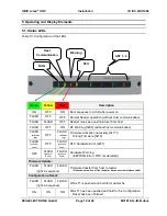
ANT 1
– 4:
Green
HF Power switched on
Blue
Tag-Detect
Red
Antenna impedance error (> 50Ohm or <50Ohm)
5.2. Reset Push Buttons
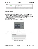
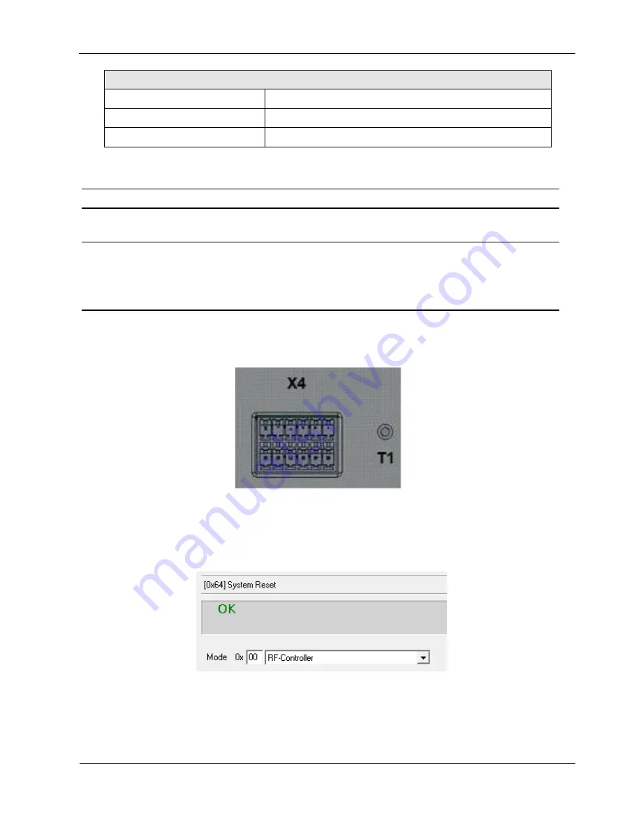
Figure 15 shows the position of the reset push button T1.
At the right side of the connector X4 the push button T1 is positioned. It is located
housing. With the push button T1 a complete configuration reset can be
a reset you should use a paper clip and push the button T1 for at least 5 s until
(left side) are switched on continuously, see 5.1. Status LEDs
Table 13: Configuration of the LEDs
Afterwards the green LED and the red LED are flashing alternating.
Figure 15: Position of the reset-switch T1
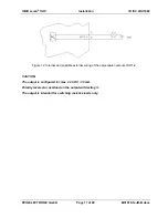
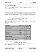
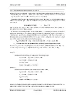
To finish the hardware configuration reset a reboot of the reader is mandatory. This can either be
performed by plugging off the power supply or by sending the command System Reset [0x64] in
Mode [0x00] RF-Controller to the reader.
Figure 16: System Reset [0x64]

