


OBID
i-
scan
®
UHF
Installation
ID ISC.LRU1002
FEIG ELECTRONIC GmbH
Page 10 of 29
M31010-1e-ID-B.docx
4.2. Power Supply
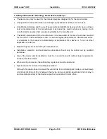
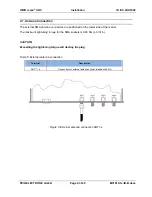
4.2.1. Power Supply via connection X2
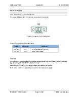
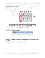
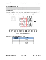
The supply voltage of 24 V DC has to be connected to Terminal X2.
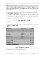
Figure 4: Connector X2 Pin Assignment
Table 6: Pin assignment for power supply
Terminal
Abbreviation
Description
X2 / Pin 1
VDC
Vcc
– supply voltage 24 V DC ±5%
X2 / Pin 2
GND
Ground
– supply voltage
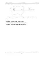
CAUTION:
The reader has to be supplied by a limited power supply (e.g. NEC Class 2/LPS power sup-
ply) according IEC EN 60950-1 chapter 2.5, only.
Reversing the polarity of the supply voltage may destroy the device.
Each reader has to be supplied by a separate external power supply.


