


OBID
i-
scan
®
UHF
Installation
ID ISC.LRU1002
FEIG ELECTRONIC GmbH
Page 13 of 29
M31010-1e-ID-B.docx
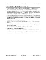
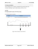
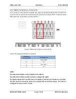
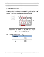
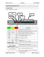
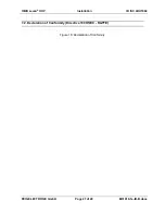
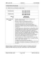
4.3.4. Data-Clock Interface on connector X4
The connection of the data-clock interface take place via the digital Outputs OUT1 and OUT2 at
connector X4. The wire for the clock needs to be connected to connector OUT1-C, the wire for the
data needs to be connected to connector OUT2-C.
Figure 8: Data-Clock Interface on connector X4
Table 9: Pin Assignment Data/Clock Interface
Pin Number
at Connector X4
Pin Assignment
7
Clock / Data-0
8
Vcc
9
Data / Data-1
10
Vcc
NOTE:
The data-clock interface is only available in Scan-Mode.
The data-clock interface cannot be used to configure the reader.
The digital outputs OUT1 and OUT2 are not available, if the data-clock interface is activated.
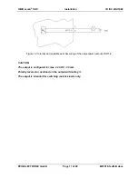
The data as well as the clock need to be supplied with an external voltage.
The output is
configured for max. 24 V DC / 30 mA.


