18
18
18
18
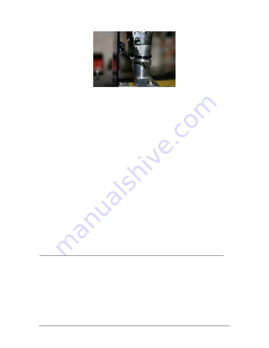
Photo 27
When you are satisfied with the operation of the outer door, add a fillet of Aeropoxy around
the wood block.
Clean up any excess glue from the struts and use a bit of touch up paint as necessary.
Run the brake lines, making sure they don’t interfere with the operation of the retract units
or doors.
Step 15: Cockpit
Now is a good time to install your batteries. In the prototype, these were attached to the
nose gear plates on either side of the nose retract. If the air tanks have not been installed
yet, place them in the nose, packed in foam.
The glare shield should not be mounted permanently to ease maintenance in the future. It
can be attached with duct tape from the inside, or if you prefer, several small dabs of silicone
glue.
The cockpit tub comes pre-trimmed, and should simply drop into place.
The canopy also comes pre-fit at the factory and should be latched in place.
Step 16: Radio Programming
The prototype was set up on 10 channels as follows:
Throttle
2 aileron
2 flap
Rudder
Elevators (use matchbox)
Nose gear steering
Brakes
Retracts
Make sure the elevator linkages are disconnected when you turn the radio on for the first time.
Begin by reversing and programming one servo, and then match the operation of the other servo
to the first, using the instructions that come with the Matchbox.
Once you are satisfied with the programming of the elevator linkages, reattach the hatch
cover with flat head screws.
Find the four small curved swash plate covers. If these have been predrilled at the factory,
match the covers up with their respective holes and screw in place with small button head
screws.
Check the operation of the elevators one last time for freedom of movement.
Step 17: CG and Control Throws


