background image

Valor

®

 Light Bar Hook-On Mounting Kit Manual

5

Valor Hook-On Mounting Kit 

Federal Signal

 www.fedsig.com

Preparing the Valor for Hook-Mounting

ROOF SUPPORT STRUCTURE: There is a roof support member that spans the distance between 

the driver and passenger side. DO NOT DRILL THROUGH THIS MEMBER! Adjust any hole locations 

until the holes can be drilled without going through this member. Failure to follow this warning will 

weaken the roof of the vehicle and may lead to an increased chance of bodily injury or death in a roll-

over accident.

DRILLING PRECAUTIONS: Before drilling holes, check the area into which you plan to drill to ensure 

that you do not damage vehicle components. All drilled holes should be deburred and all sharp 

edges should be smoothed. Additionally, all exterior drilled holes must be sealed with Motorcraft 

seam sealer T-A-2-B or equivalent to prevent the potential exposure to carbon monoxide or other 

potentially harmful fumes. Failure to observe this warning could cause serious injury or death.

IMPORTANT: 

Plan all cable routing before completing the installation. Plan the location of the wirerouting hole 

in the vehicle roof so that the power and communication cables do not have tight bends and have some slack 

to allow disconnection on removal.
Before proceeding, refer to the instructions provided with the separately purchased mounting hook kit. To 

prepare the light bar for hook-mounting:

1. 

Place the light bar assembly on the vehicle roof at the selected location. Usually the assembly is installed 

so that the mounting hooks attach at, or immediately behind, the door center post.

2. 

Adjust both mounting foot assemblies in or out until the mounting pads rest near the edge of the roof or 

gutter where the roof is the most rigid.

3. 

Center the light bar assembly so that the end of the assembly and edge of the roof are equidistant on 

each side of the vehicle. Ensure that the gutter hooks, when installed, will not interfere with the door or 

door glass. Improper clamping on the vehicle roof may result if the gutter hooks contact the Mounting feet. 

Adjust the mounting feet, if required, before tightening the 5/16-inch hex nuts.

4. 

Remove the light bar assembly from the vehicle roof and place it on soft rags or cardboard to avoid 

marring the plastic domes.

5. 

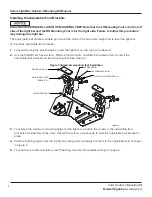
Turn the light bar assembly over so that the bottom of the assembly faces up. Tighten the eight  

5/16-inch nuts (four on each mounting foot) installed in step 2 in "Installing the Service Kit Mounting Feet" 

on page 2.

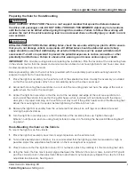
Hook-Mounting the Valor on the Vehicle

To mount the light bar on the vehicle:

1. 

Place the light bar assembly back into its original position on the vehicle roof.

2. 

To maximize aerodynamic efficiency, it is recommended that the lighting system be mounted as high as 

possible. Adjust the adjustable foot brackets on the mounting foot as required.

3. 

Check to ensure that the light bar is level. If it is not level, adjust it by rotating it in the mounting foot slots.

4. 

Using the holes that are most closely aligned between the 5/16-inch Torx pan screws, install a #10 Type B 

pan Torx screw to lock in the adjustment. Minor adjustment may be necessary. Repeat this step for all four 

adjustable foot brackets. See Figure 4. 

Содержание Valor Hook-On

Страница 1: ...effectiveness of the airbag or potentially dislodge the equipment causing serious injury to you or others To avoid damage to the light bar do not overtighten screws and nuts This product contains high intensity LED devices To prevent permanent eye damage DO NOT stare into the light beam at close range For additional precautions and information refer to the instructions packed with related products...

Страница 2: ...t Failure to heed this warning may cause personal injury Installing the Service Kit Mounting Feet ENSURE PROPER INSTALLATION OF MOUNTING FEET Before installing the mounting feet and hook attach bracket note that the LH foot and bracket is for the left side of the light bar and the RH foot and bracket for the right side Failure to follow this precaution may damage the light bar The Service Kit requ...

Страница 3: ...290A6440 3 Use a nut retainer and two 10 Type B pan Torx screws to trap the 5 16 18 flange nut on the backside of the hook attach bracket See Figure 2 Figure 2 Hook attach bracket installation 10 PAN TORX SCREW 4 290A6441 LH HOOK ATTACH BRACKET LH MOUNTING FOOT 5 16 18 FLANGE NUT 2 NUT RETAINER 2 LIGHTBAR BASE 4 Repeat steps 2 and 3 with the other mounting foot assembly 5 To continue with the inst...

Страница 4: ...soft rags or cardboard 2 Use the 5 16 18 Torx head screws 5 16 inch flat washers and 5 16 inch lockwashers to install the adjustable foot brackets on the mounting feet See Figure 3 Figure 3 Adjustable mounting feet installation 5 16 18 PAN TORX SCREW 8 5 16 LOCKWASHER 8 5 16 WASHER 8 MOUNTING PAD 4 ADJUSTABLE FOOT BRACKET 4 LH MOUNTING FOOT 290A6444 3 To achieve the maximum mounting height of the ...

Страница 5: ...he assembly is installed so that the mounting hooks attach at or immediately behind the door center post 2 Adjust both mounting foot assemblies in or out until the mounting pads rest near the edge of the roof or gutter where the roof is the most rigid 3 Center the light bar assembly so that the end of the assembly and edge of the roof are equidistant on each side of the vehicle Ensure that the gut...

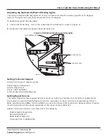
Страница 6: ...e tight Figure 4 Light bar mounted on vehicle roof 5 16 18 PAN TORX SCREW 8 LED ALLEY LIGHT ADJUSTABLE FOOT BRACKETS 4 10 TYPE B PAN TORX SCREW 4 LH MOUNTING FOOT 290A6445 SLOTS FOR LEVELING LIGHTBAR AND ADJUSTING HEIGHT FOOTPAD 4 Aiming the Optional HotFoot LED Takedown Lights The optional HotFoot LED takedown lights are factory installed and wired The horizontal aim of the takedown light is adju...

Страница 7: ... KEPS NUTS 290A6451 LED ALLEY LIGHT Getting Technical Support For technical support please contact Federal Signal Corporation Service Department Phone 1 800 433 9132 Email empserviceinfo fedsig com Getting Repair Service The Federal Signal factory provides technical assistance with any problems that cannot be handled locally Any product returned to Federal Signal for service inspection or repair m...

Страница 8: ...ty This product is subject to and covered by a limited warranty a copy of which can be found at www fedsig com SSG Warranty A copy of this limited warranty can also be obtained by written request to Federal Signal Corporation 2645 Federal Signal Drive University Park IL 60484 email to info fedsig com or call 1 708 534 3400 This limited warranty is in lieu of all other warranties express or implied...

Отзывы: