


Page 6 of 91
Rev. 4.20
1.1 GENERAL CHARACTERISTICS
The fire-prevention control panel was designed in observance to the rules EN54-2 and EN54-4, and it has the
following characteristics:
•
The available versions of the control panel are at 1 – 2 – 4 loops.
•
It is possible to address on a single loop up to 127 points (detectors, buttons, Input/output modules and
isolators), distributed like as follows:
1.
Up to 120 points among detectors, buttons and Input/output modules;
2.
Up to 7 isolator modules of line, which will take the addresses from 121 to 127 and they are
compulsory to conform with the regulations at least with every 32 detectors systems, buttons and
Input/output modules;
3.
Un-addressed infinite detectors that will refer to point “0”.
•
The installation of a control panel at 2 loops allows to install a total of 254 points with the possibility to
address up to 120 points among detectors, buttons and Input/output modules on each single loop.
•
The addressing for the assignment to the detectors, buttons and Input/output modules is free (see
example in
PART 5).
•
The line isolators are addressed through automatic procedure directly by the control panel, assigning in
progression the addresses from 121 to 127.
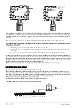
The power supply and the communication to the device occurs through only two cables. A twisted and shielded
cable must be used in each loop.
Connectible detectors:
Smoke detector:
EX-SOD, EX-SD
Heat detector:
EX-TD
Multi-criteria detector:
EX-MD
Connectable modules:
Manual button:
EX-P5, EX-MP
Input / Output module:
EX-MEIO
Isolator module:
EX-MEIS
(discontinued)
Passive isolator module:
EX-ISO
Cables used for connections:
Shielded and twisted cable 0,5 mm
2
CABR205
Shielded and twisted cable 1 mm
2
CABR21
Shielded and twisted cable 1,5 mm
2
CABR215
Ø
The detectors use a system of digital communication, a low frequency of communication and revelation
elements of errors that become highly free of interferences. The protocol has a special system of
communication (polling system) which allows a quick answer in case of alarm (127 points scanner in less than
half a second) and allows the control of the status, the analogic value and the working parameters of
detectors.
Ø
Loop can be subdivided into 63 zones per loop; each of them can contain one or more devices. A numerical
address must be assigned to each element of the loop. The address programming in the points occurs
through the control of the panel itself.
Ø
The control panel has a retro-illuminated alphanumeric display at liquid crystals 8x21, characters for the
signal display and the programming of control panel. Faults and alarms are displayed through suitable
luminous leds. It is possible to display the analogic level of each detector, the detector type and the belonging
zone. The historical memory can total up to 1000 single or combined events carrying date and hour.
PART 1
DETAILS
Содержание EX-CP4L
Страница 5: ...Page 5 of 91 Rev 4 20...
Страница 64: ...Page 64 of 91 Rev 4 20 MOXA DE 211 module...