


Page 11 of 91
Rev. 4.20
For the connection to the power supply clips, the electrical conductors must be terminated between terminal clips,
at scope to have in any case a electrical security condition.
2.4.3 Assembly
After having mounted the panel in the most appropriate place, verify proper cabling to adopt and where to run it:
•
the rectangle holes on the case back;
•
the round holes are normally closed on the top part of the metal case.
In the case the round pre-fitted holes aren’t utilized; please leave them closed so to prevent any metallic or other
pieces to fall into the metal case so that you may prevent damages to the electronic card inside.
In case you change the cable access to the metal case; make sure that the holes are closed off so to prevent any
possibility of damages to the electronic card.
As for the actual mounting; proceed in the following manner making sure that there is no mains power line or any
current connected:
1.
open the front cover by unscrewing the four screws on every corner 4x16;
2.
only if you plan to pass the cables through the top holes; then you punch the pre-cut holes to access the
cabinet;
3.
fix the metallic case by the three fixing/access points (first the middle one, then the two on the lower part);
one may also use the other two fixing holes on the top part in order to ensure a stronger fixing to the
surface;
4.
introduce the cables into the metallic case in a most orderly fashion so that they are well sorted and
separated (follow the instruction reported on the previous page) so they do not run under the electronic
card.
5.
proceed in inserting all the electrical connections as described on this manual;
6.
close the front cover by re-screwing all the screws provided.
In the case the electronic card should be completely removed and /or re-inserted into the metallic case; pay extra
attention to the ground wire with cable endings "ring type" secured by soldered steel nuts to host the metal screws
4x20 directly on the metallic case.
When the electronic card is re-inserted, re-apply the ground cabling as they were originally: if not executed in this
way the electric safety conditions may be jeopardized.
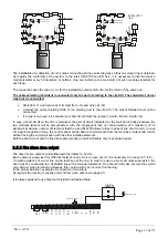
2.5 CONNECTION
The motherboard of the control panel in picture 2. The positions of the clips and fuses are pointed out. Besides
the connector PS2 for the keyboard and the grey button of resetting to push at the first starting of the control
panel are pointed out.
The left clips concern the control panel outputs (see charter
PART 9 page 45), and exactly:
Ø
(out5) Clips RL1 (SEL4): relay 1 is a clean relay no supervised that can be programmed NO/NC;
Ø
(out4) Clips RL2 (SEL3): relay 1 is a clean relay no supervised that can be programmed NO/NC;
Ø
(out9) Clips OC4: open collector No 4 programmable for typology of alarm and zone;
Ø
(out8) Clips OC3: open collector No 3 programmable for typology of alarm and zone;
Ø
(out7) Clips OC2: open collector No 2 programmable for typology of alarm and zone;
Ø
(out6) Clips OC1: open collector No 1 programmable for typology of alarm and zone;
Ø
(out3) Clips FAULT (SEL1,2): supervised output of fault;
Ø
(out2) Clips –S +S: supervised siren;
Ø
(out1) Clips +24 –24: auxiliary power supply 24Vdc.
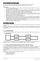
WARNING
: after the cable connection of the power supply to the GND-N-L clips of AC-DC Adaptor, it is important
to immobilize the three electrical cables with a plastic strip. It is necessary to prevent that electrical cables are free
to move.
WARNING
: the power supply cable must have the ground electrical cable (GND) more long respect the line (L)
and neuter (N) cables.
Содержание EX-CP4L
Страница 5: ...Page 5 of 91 Rev 4 20...
Страница 64: ...Page 64 of 91 Rev 4 20 MOXA DE 211 module...