12
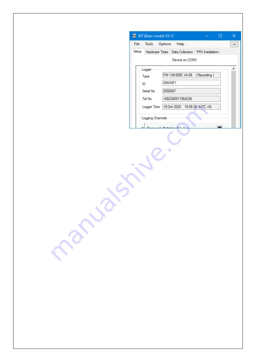
IDT will now display 4 tabs.
Within any tab, information is divided into
various areas, or “panels”.
T
he “Setup” tab
is used for displaying:
•
Details of the Sentinel 2 unit.
•
The current program settings of the
unit.
The panel labelled “Logger”
shows:
•
The software version running on the
unit (here it is shown as V4.88).
•
Whether the logger built into the unit
is:
o
(Stopped).
o
(Waiting).
o
(Recording).
•
The control unit’s serial number.
•
The telephone number of the device displays the SIM card number of the device, if
factory fitted.
•
The logger date and time … this is the local time for wherever the logger is installed.
The offset of local time from UTC is shown in brackets.
Any greyed-out fields indicates the user cannot adjust them, typically for factory-set
parameters. Any non-greyed areas indicate the user can edit the field.
The user can insert a “Site
-
ID” for this location, which is in the format of a 7
-digit
reference number.
Other panels (not shown here) follow-on, with settings for various aspects
of the unit’s
functionality.
The
“Hardware Test” / “Data Collection” / ”PRV Installation” tabs shown in the above
image provide access to information, settings, and control functions available in
Sentinel 2 and will be explained later in this manual.
e.g.
The “PRV Installation” tab is used during installation.
It can provide live flow and pressure data or manual over-ride controls for various
components of the system.
Содержание Sentinel 2
Страница 29: ...29 3 2 STANDARD INSTALLATIONS 2 POINT PRESSURE CONTROL 3 2 1 Using internal transducers Upstream pressure 90 m...
Страница 30: ...30 3 2 2 Using external pressure transducers Upstream pressure 90 m...
Страница 31: ...31 3 2 3 Using internal transducers Upstream pressure 90 m...
Страница 32: ...32 3 2 4 Using external pressure transducers Upstream pressure 90 m...


