


6th edition, 22.05.2023
7000.05060, 6th edition, 22.05.2023
7000.05060
Installation
24
4.2.2
Drive connections
The maximum length of the cable between the Motion Controller and motor depends on
the sensor system used and the electrical and magnetic fields in the environment.
Tab. 8:
Guide values for the cable length
Longer connection cables are generally permissible, but must be validated for the target
installation.
Optimization of the behavior in respect of transient emission and interference resistance
may require additional EMC measures (see chap. 4.3, p. 43).
4.2.3
Connection of the power supply
Discrete inputs and outputs (for instance for discrete set-point specification or for con
-
nection of limit switches and reference switches)
Communication connections
Make sure that the connection cables on the connection side are not longer than 3 m.
Keep the shield connections for connection cables short and flat.
To reduce the effects on the DC power supply network, ferrite sleeves (such as WE 742 700
790) can be used on the supply cables.
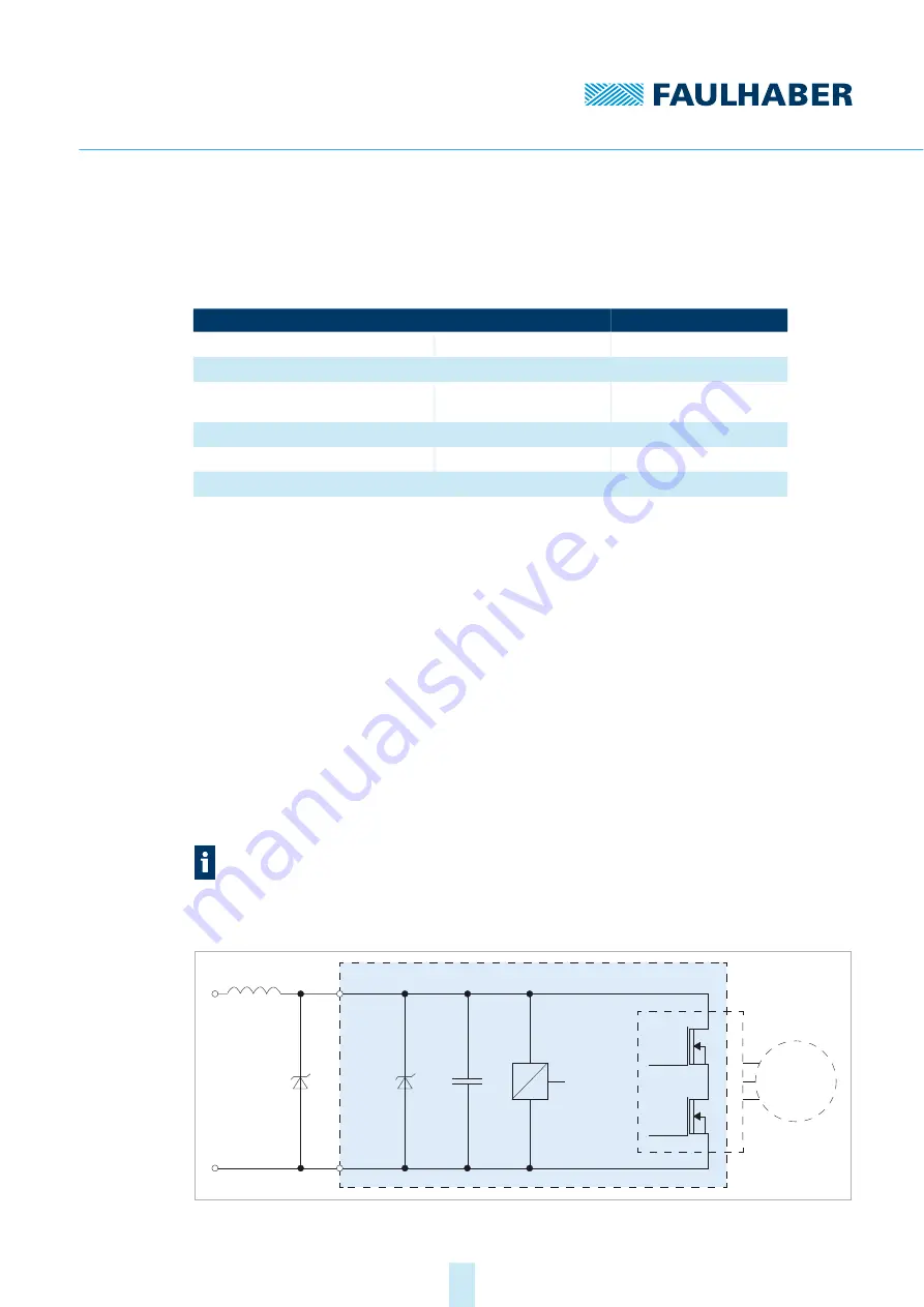
Fig. 12: EMC suppressor circuit
Encoder type
Unshielded length
Shielded length
a)
a)
applies to cables separately shielded from the motor phase power cables.
Digital Hall sensors
0.5 m
2–5 m
Analog Hall sensors
0.5 m
2–5 m
Incremental encoders without line
driver
0.5 m
2–5 m
Incremental encoders with line driver
2 m
2–5 m
b)
b)
For position encoders with Line Driver interface, the cables must be shielded, twisted pairs
Absolute encoders without line driver
0.3 m
0.5 m
Absolute encoders with line driver
2 m
5 m
b)
The USB port is a pure configuration connection. A cable length of < 3 m also applies
for the USB connection.
L1
D1
G
ND
Motor
Int.
S
upply
U
P