


2010-06-30
Page 21 of 42
IT430_Tech_doc.doc
4.6.1 Active GPS antenna
The customer may use an external active GPS antenna when antenna cable loss exceeds > 1dB.
It is suggested the active antenna has a net gain
including cable loss
in the range from +6 dB to
+25 dB. Specified sensitivity is measured with external low noise (NF=1dB) amplifier, which gives
about 2dB advantage in sensitivity when compared to a passive antenna.
An active antenna requires certain bias voltage, which can be supplied externally via VDD_ANT
supply input. De-couple externally the VDD_ANT input; see the application circuit diagram in
chapter 6. The external bias supply must provide limitation of the max current below 150mA
during e.g. antenna signal short circuit condition.
When the module is in Hibernate state, the antenna bias can be switched off externally by using
WAKEUP signal output to switch off VDD_ANT supply, see e.g. Application Circuit Diagram.
NOTE
With Active GPS Antenna provide externally VDD_ANT
supply suitable for the active antenna used. The VDD_ANT
supply must provide also short circuit protection externally,
rated current 70mA, abs. max 150mA.
4.6.2 Jamming Remover
Jamming Remover is an embedded HW block that tracks and removes up to 8 pcs CW (Carrier
Wave) type signals up to -90 dBm signal levels.
Jamming Remover can be used for detecting and solving EMI problems in the customer’s system
and it is effective against e.g. narrow band clock harmonics. Use PC utility SiRFLive to indicate
and detect CW EMI signals, see SiRFLive user manual for details.
Note that Jamming Removal is not effective against wide band noise like EMI, which increases
effective noise floor and reduces GPS signal levels.
4.7 Dead Reckoning I
2
C bus
The DR_I
2
C bus (master) provides optional connectivity to Dead Reckoning sensors (e.g. 3-D
Accelerometer). The bus supports also optional connectivity to EEPROM for Client Generated
Extended Ephemeris (CGEE) data storage and ROM patch code upload during power up boot
and after waking up from Hibernate state. The accelerometer sensor provides stationary
detection, which allows to reduce the position spread when stationary with weak GPS signals e.g.
indoors. Other features will follow like Pedestrian DR. When sensor is used connect also the
sensor’s INT output to IT430’s EIT2 input. The bus signals require external pull up resistors
2.2kohm on both signals and can be left not connected when not used.
DR I²C interface supports:
■
Common sensor formats (Kionix, KXTF9 device)
Содержание IT430
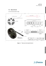
Страница 24: ...2010 06 30 Page 24 of 42 IT430_Tech_doc doc Figure 3 Dimensions ...
Страница 38: ...2010 06 30 Page 38 of 42 IT430_Tech_doc doc 7 3 Circuit drawing ...
Страница 39: ...2010 06 30 Page 39 of 42 IT430_Tech_doc doc 7 4 Assembly drawing Top side 7 5 Artwork layer 1 Top ...
Страница 40: ...2010 06 30 Page 40 of 42 IT430_Tech_doc doc 7 6 Artwork layer 2 7 7 Artwork layer 3 ...
Страница 41: ...2010 06 30 Page 41 of 42 IT430_Tech_doc doc 7 8 Artwork layer 4 Bottom ...


